Car Radio Repair Masterclass
Vintage tube and hybrid radios, transistor receivers with cassette or CD mechanisms, and modern head units with vehicle integration. Learn to identify the design, distinguish faults and prepare a documented repair plan.
Transistor Car Radios & Tape/CD Receivers
Low-voltage bench planning, power, reception, audio, controls and mechanical media systems.
System map and practical route
Original course study map. Connector assignments, voltage limits and service procedures must come from the exact model manual.
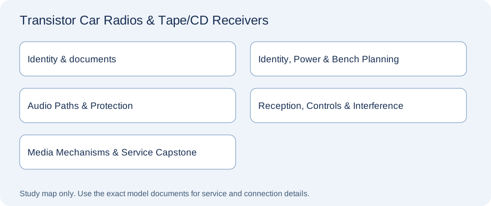
Begin with the two free previews. Work through the mini courses, keep a repair-planning portfolio, then submit the capstone worksheet for qualified review. Quizzes record written learning only.
Identity, Power & Bench Planning
Four original written lessons with learner Q&A, a diagnostic checklist, fictional cases and verification tasks.
4 lessons • included in this full track and the complete program
Open mini course →View price & enrollAudio Paths & Protection
Four original written lessons with learner Q&A, a diagnostic checklist, fictional cases and verification tasks.
4 lessons • included in this full track and the complete program
Open mini course →View price & enrollReception, Controls & Interference
Four original written lessons with learner Q&A, a diagnostic checklist, fictional cases and verification tasks.
4 lessons • included in this full track and the complete program
Open mini course →View price & enrollMedia Mechanisms & Service Capstone
Four original written lessons with learner Q&A, a diagnostic checklist, fictional cases and verification tasks.
4 lessons • included in this full track and the complete program
Open mini course →View price & enrollFind a car-radio lesson, symptom or question
Search titles and learner questions. Lesson access follows your existing mini-course, full-track or complete-program purchase.
- Free preview: Identify a transistor car radio and its systemIdentity, Power & Bench Planning • Free sample
- Free preview: Power, ground and switched control inputsIdentity, Power & Bench Planning • Free sample
- No-start diagnosis and protective fusesIdentity, Power & Bench Planning • Included lesson
- Approved bench supplies and current-limit planningIdentity, Power & Bench Planning • Included lesson
- No sound: settings, signal path or load?Audio Paths & Protection • Included lesson
- Speaker-output topology and safe referencesAudio Paths & Protection • Included lesson
- Distortion, clipping and gain relationshipsAudio Paths & Protection • Included lesson
- Thermal shutdown and protection behaviorAudio Paths & Protection • Included lesson
- AM and FM reception: compare before aligningReception, Controls & Interference • Included lesson
- Antenna connectors and powered antenna systemsReception, Controls & Interference • Included lesson
- Controls, crackling and intermittent connectionsReception, Controls & Interference • Included lesson
- Engine-related whine and vehicle interferenceReception, Controls & Interference • Included lesson
- Cassette belts, rollers and tape handlingMedia Mechanisms & Service Capstone • Included lesson
- CD loading, reading and laser precautionsMedia Mechanisms & Service Capstone • Included lesson
- Parts selection, soldering scope and ESDMedia Mechanisms & Service Capstone • Included lesson
- Transistor-radio service capstoneMedia Mechanisms & Service Capstone • Included lesson
No matching lessons. Try a shorter symptom or circuit name.
Free preview: Power, ground and switched control inputs
Learning goal: Explain power, ground and switched control inputs and prepare an evidence-led diagnostic plan.
Constant supply, ignition-related control and ground can have distinct roles, depending on the design. A receiver may need more than one condition to operate. Document the required connection rather than relying on wire color alone. Supply availability without a load does not necessarily establish the quality of a current-carrying connection.
Use the exact installation information; do not join unidentified wires to make a receiver start.
For the written exercise, identify the exact equipment and relevant documents. Separate recorded observations from assumptions, then list at least two plausible explanations and what would distinguish them. Do not invent measurements or apply a generic wiring assignment to customer equipment. Practical work requires suitable training and the model-specific procedure.
Diagnostic planning checklist
- Identify receiver, revision, vehicle or bench context and relevant accessories.
- Record the specific symptom, source and timing without inventing internal findings.
- Compare the documented design with at least two competing explanations.
- Name the evidence needed and the appropriate qualified or supervised assessment.
- Define verification for the original complaint and any agreed retained functions.
Questions learners ask
Can color alone identify every wiring function?
No. Colors are clues only when confirmed by the matching documentation.
What should the case report avoid?
For this lesson, avoid replacing documentation with the shortcut: Use the exact installation information; do not join unidentified wires to make a receiver start.
Car Radio service glossary
- ACC
- A documented ignition-related control function; not a universal wire assignment.
- AGC
- Automatic gain control in a receiver.
- AM
- Amplitude modulation; distinguish band reception from the audio output path.
- Antenna adapter
- An interface whose compatibility and any power requirements must be checked.
- B+
- An operating supply in tube circuitry; it can be hazardous despite a low-voltage input.
- Bias
- The operating condition of an active stage.
- Bridge output
- An output arrangement in which both load terminals can be driven.
- Buffer capacitor
- A circuit-specific component associated with switching-supply behavior.
- Chassis
- Receiver assembly or its identifier; not necessarily the cabinet or vehicle identity.
- Clipping
- Signal limitation that changes the intended waveform.
- Crossover
- Processing that distributes or limits frequency ranges.
- ESD
- Electrostatic discharge that can damage susceptible electronics.
- Fader
- Front/rear level relationship, where supported.
- FM
- Frequency modulation; its reception path can differ from AM.
- Ground polarity
- The documented relationship between the supply and reference chassis.
- Head unit
- The receiver/control assembly in a car audio system.
- IF
- Intermediate-frequency processing after frequency conversion.
- Line level
- A signal interface distinct from power speaker outputs.
- Mute
- A function that suppresses audio; its cause and control are design-specific.
- OEM
- Original-equipment manufacturer; installed options still need identification.
- Pinout
- Connector assignments for an exact model and revision.
- Remote enable
- A documented control condition for compatible external equipment.
- Ripple
- Variation on a supply level.
- Rollback
- A documented return to a known software or configuration state.
- Source chain
- All devices and connections between content and the receiver.
- Synchronous vibrator
- A historical vibrator arrangement including a rectifying function.
- Vibrator
- An electromechanical switching component used in some historical supplies.
- Voltage drop
- Difference across a current-carrying path due to its impedance.
Diagnostic case
A radio loses memory and fails to follow the key state after undocumented harness changes.
Fictional training case; the observations are not measurements from your car radio.
Practice task / worksheet
Write a case report with identity, the complaint, two competing explanations, missing evidence, an approved assessment scope and verification criteria. Explain why the rejected shortcut would not establish a reliable diagnosis.
Printable diagnostic worksheet
- Model, chassis and revision
- _______________________________
- Symptom and when it occurs
- _______________________________
- Evidence versus assumptions
- _______________________________
- Three competing hypotheses
- _______________________________
- Documentation and qualified assessment required
- _______________________________
- Approved scope and verification criteria
- _______________________________
Check your reasoning
Can color alone identify every wiring function?
No. Colors are clues only when confirmed by the matching documentation. The goal is a supported conclusion, with uncertainty preserved where evidence is missing.
References and further reading
Original written lessons and fictional diagnostic cases. Manufacturer service procedures must be obtained for the exact equipment; linked manuals are not resold as course downloads.
Save to Pinterest