Electronic Components & Circuits
A broad reference to parts, instruments and circuit functions, explained in everyday language with labeled illustrations, examples and specification checks.
How to use this list
Open an entry to see its illustration, what it does, an example and the specifications that matter. Tap any image to enlarge it. Images are original representative illustrations, not photographs, exact pinouts or guarantees of physical identification. Component families and circuit arrangements are distinct: a capacitor is a part; a filter is a circuit that may use several parts. This reference covers common and important families, rather than every manufacturer part number or specialized circuit ever made.
Examples explain function; they are not universal replacement or wiring instructions. Appearance, package size and a matching nominal value do not establish compatibility. Stored charge, mains, vehicle batteries and high-voltage equipment require appropriate precautions and qualified procedures.
Search the free reference
160 of 160 entries shown. Search matches all entered words across names and explanations.
Browse by category
Accelerometer and gyroscopeSensors and Transducers
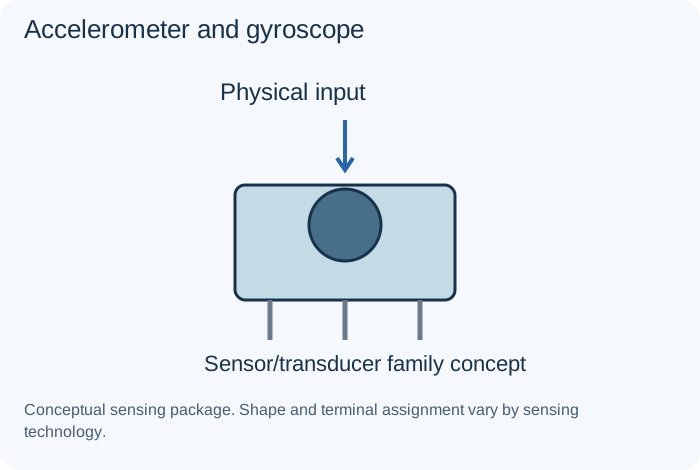
What it does
Measure acceleration-related and angular-rate-related quantities through their specified sensing systems.
Example
Motion monitoring.
Important distinction
Axes, range, calibration and interface must be interpreted correctly.
Specifications to read
Measured quantity/reference, range, accuracy, response, supply/bias, interface, calibration and environment.
A rating is a limit or condition, not a guarantee of suitability. Use the manufacturer's data sheet for the exact component and the equipment's schematic for its intended role.
ADC and DACIntegrated Circuits
What it does
An ADC converts an analog input into digital information; a DAC converts digital information into an analog output.
Example
Sensor measurement or audio conversion.
Important distinction
Resolution is not the same as total accuracy, bandwidth or noise performance.
Specifications to read
Exact part/revision, pinout, supply, input/output ranges, timing, interface, thermal limits and required surrounding parts.
A rating is a limit or condition, not a guarantee of suitability. Use the manufacturer's data sheet for the exact component and the equipment's schematic for its intended role.
Aluminum electrolytic capacitorCapacitors
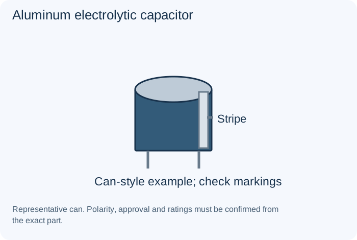
What it does
Provides relatively large capacitance in a compact package; many common versions are polarized.
Example
Bulk supply smoothing.
Important distinction
Polarity, ripple-current capability, ESR and temperature requirements matter.
Specifications to read
Capacitance (F), tolerance, voltage, polarity, dielectric, ESR, leakage, ripple capability and temperature conditions.
A rating is a limit or condition, not a guarantee of suitability. Use the manufacturer's data sheet for the exact component and the equipment's schematic for its intended role.
Analog switch and multiplexerIntegrated Circuits
What it does
Routes suitable signals under control of its supported logic interface.
Example
Selecting sensor inputs.
Important distinction
Signal range, on-resistance and leakage constrain use.
Specifications to read
Exact part/revision, pinout, supply, input/output ranges, timing, interface, thermal limits and required surrounding parts.
A rating is a limit or condition, not a guarantee of suitability. Use the manufacturer's data sheet for the exact component and the equipment's schematic for its intended role.
Audio, motor and interface driver ICIntegrated Circuits
What it does
Provides application-specific drive or communication functions rather than a universal amplification role.
Example
An audio output, motor stage or serial interface.
Important distinction
Choose by the exact circuit function, protection and interface requirements.
Specifications to read
Exact part/revision, pinout, supply, input/output ranges, timing, interface, thermal limits and required surrounding parts.
A rating is a limit or condition, not a guarantee of suitability. Use the manufacturer's data sheet for the exact component and the equipment's schematic for its intended role.
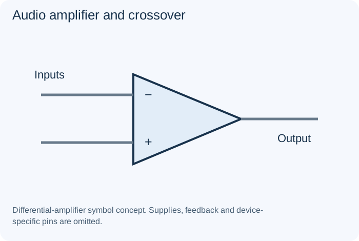
Audio amplifier and crossoverCommon Circuits
What it does
Amplification supplies signal power from a source; crossover processing divides or limits frequency ranges.
Example
A speaker system.
Important distinction
Speaker-level, line-level and processing connections have different requirements.
Specifications to read
Intended function, source/load, operating range, component limits, response, stability, protection and layout.
A rating is a limit or condition, not a guarantee of suitability. Use the manufacturer's data sheet for the exact component and the equipment's schematic for its intended role.
Audio and pulse transformerInductors and Transformers
What it does
A transformer optimized for audio bandwidth or pulse transfer rather than simply mains frequency.
Example
An audio output stage or pulse interface.
Important distinction
Frequency response, insulation and loading requirements differ by application.
Specifications to read
Inductance, winding resistance, current, saturation, frequency, losses, coupling and required insulation.
A rating is a limit or condition, not a guarantee of suitability. Use the manufacturer's data sheet for the exact component and the equipment's schematic for its intended role.
Autotransformer and adjustable autotransformerInductors and Transformers
What it does
Uses a shared winding arrangement. Some adjustable versions vary an output voltage.
Example
Qualified supply adjustment.
Important distinction
Voltage adjustment does not by itself provide electrical isolation.
Specifications to read
Inductance, winding resistance, current, saturation, frequency, losses, coupling and required insulation.
A rating is a limit or condition, not a guarantee of suitability. Use the manufacturer's data sheet for the exact component and the equipment's schematic for its intended role.
Band-pass and notch filterCommon Circuits
What it does
A band-pass emphasizes an intended band; a notch reduces an intended region.
Example
A receiver stage or interference treatment.
Important distinction
Center frequency, bandwidth and rejection describe different properties.
Specifications to read
Intended function, source/load, operating range, component limits, response, stability, protection and layout.
A rating is a limit or condition, not a guarantee of suitability. Use the manufacturer's data sheet for the exact component and the equipment's schematic for its intended role.
Battery management and chargerPower Sources and Outputs
What it does
A system manages charging and relevant protection/monitoring for a specified cell arrangement.
Example
A rechargeable product.
Important distinction
Cell chemistry, series count and sensing arrangements must match the design.
Specifications to read
Source/load compatibility, polarity, current, chemistry where relevant, interface, mechanical and thermal conditions.
A rating is a limit or condition, not a guarantee of suitability. Use the manufacturer's data sheet for the exact component and the equipment's schematic for its intended role.
Bench supply and electronic loadTest Equipment
What it does
A bench supply provides controlled power; an electronic load draws power in supported modes.
Example
A supervised low-voltage test system.
Important distinction
Current limiting and load modes do not remove the need for suitable ratings and an approved setup.
Specifications to read
Supported modes, input limits, probes, reference/ground, bandwidth or test conditions and appropriate training.
A rating is a limit or condition, not a guarantee of suitability. Use the manufacturer's data sheet for the exact component and the equipment's schematic for its intended role.
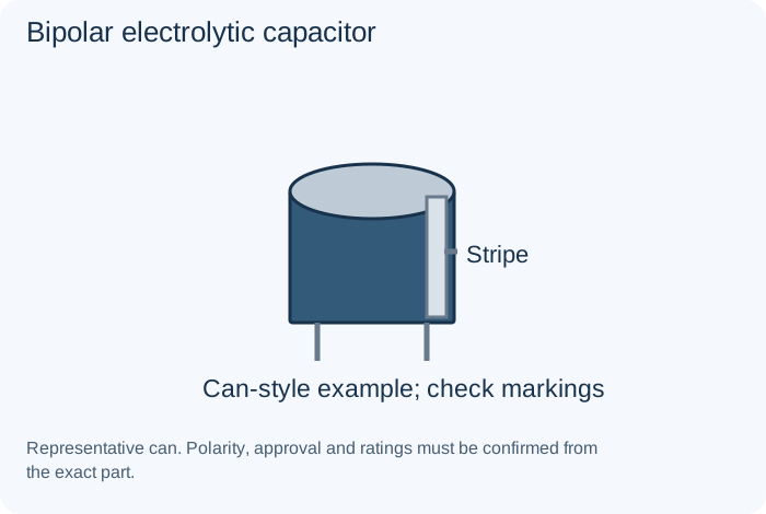
Bipolar electrolytic capacitorCapacitors
What it does
Designed for applications without a fixed capacitor polarity within its specified limits.
Example
An appropriate audio network.
Important distinction
Bipolar does not mean suitable for arbitrary mains or pulse service.
Specifications to read
Capacitance (F), tolerance, voltage, polarity, dielectric, ESR, leakage, ripple capability and temperature conditions.
A rating is a limit or condition, not a guarantee of suitability. Use the manufacturer's data sheet for the exact component and the equipment's schematic for its intended role.
Boost converterCommon Circuits
What it does
A switching topology used to raise an applicable input to an intended output.
Example
A portable-device rail.
Important distinction
Voltage conversion does not create energy; source current and efficiency constrain operation.
Specifications to read
Intended function, source/load, operating range, component limits, response, stability, protection and layout.
A rating is a limit or condition, not a guarantee of suitability. Use the manufacturer's data sheet for the exact component and the equipment's schematic for its intended role.
Bridge rectifierDiodes
What it does
Combines four diode functions to obtain full-wave rectification with a defined input and output arrangement.
Example
A supply's rectification stage.
Important distinction
Rectified voltage still needs appropriate regulation or filtering when required.
Specifications to read
Forward/reverse voltage behavior, current, dissipation, recovery or response and application-specific limits.
A rating is a limit or condition, not a guarantee of suitability. Use the manufacturer's data sheet for the exact component and the equipment's schematic for its intended role.
Buck-boost and SEPIC converterCommon Circuits
What it does
Topology families that can support output requirements across changing input relationships.
Example
A supply with a variable input.
Important distinction
Output polarity and operating characteristics depend on the selected arrangement.
Specifications to read
Intended function, source/load, operating range, component limits, response, stability, protection and layout.
A rating is a limit or condition, not a guarantee of suitability. Use the manufacturer's data sheet for the exact component and the equipment's schematic for its intended role.
Buck converterCommon Circuits
What it does
A switching topology used to produce a lower regulated output from an applicable input.
Example
An efficient step-down rail.
Important distinction
Switching design needs coordinated magnetics, controls, protection and layout.
Specifications to read
Intended function, source/load, operating range, component limits, response, stability, protection and layout.
A rating is a limit or condition, not a guarantee of suitability. Use the manufacturer's data sheet for the exact component and the equipment's schematic for its intended role.
Buffer and differential amplifierCommon Circuits
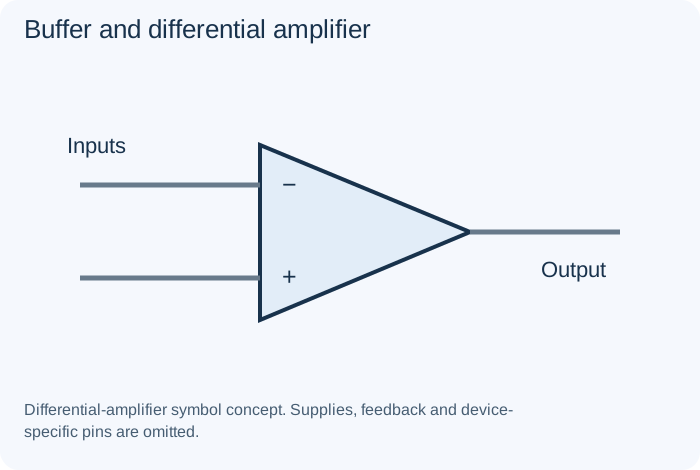
What it does
A buffer reduces interaction between stages; a differential amplifier responds to a signal difference.
Example
A sensor interface.
Important distinction
Common-mode range, loading and accuracy still matter.
Specifications to read
Intended function, source/load, operating range, component limits, response, stability, protection and layout.
A rating is a limit or condition, not a guarantee of suitability. Use the manufacturer's data sheet for the exact component and the equipment's schematic for its intended role.
BuzzerPower Sources and Outputs
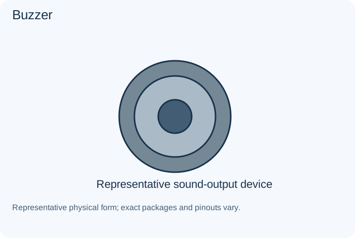
What it does
Produces an audible indication using an internal or externally supplied drive arrangement.
Example
An alarm or status sound.
Important distinction
Active and passive buzzer types require different drive signals.
Specifications to read
Source/load compatibility, polarity, current, chemistry where relevant, interface, mechanical and thermal conditions.
A rating is a limit or condition, not a guarantee of suitability. Use the manufacturer's data sheet for the exact component and the equipment's schematic for its intended role.
C0G and NP0 ceramic dielectricCapacitors
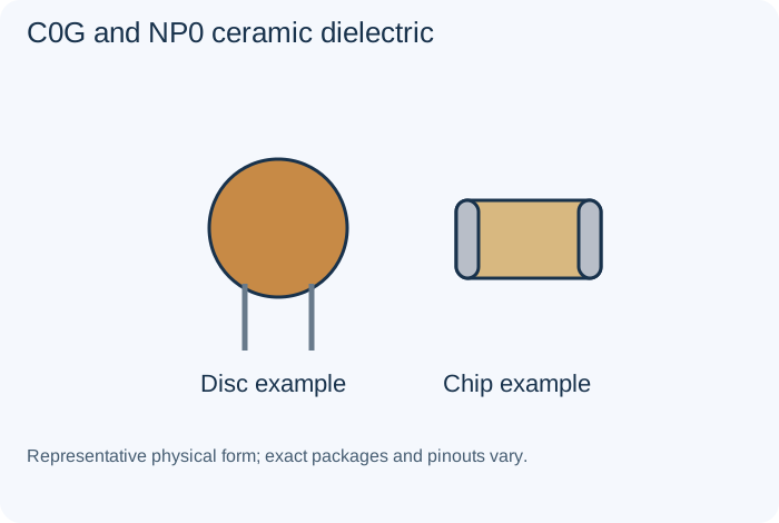
What it does
Temperature-compensating ceramic classification commonly selected where capacitance stability matters.
Example
A suitable tuning or precision timing application.
Important distinction
Capacitance, voltage and specific series limits must still be checked.
Specifications to read
Capacitance (F), tolerance, voltage, polarity, dielectric, ESR, leakage, ripple capability and temperature conditions.
A rating is a limit or condition, not a guarantee of suitability. Use the manufacturer's data sheet for the exact component and the equipment's schematic for its intended role.
Cable, shielding and twisted pairSwitches, Relays and Connectors
What it does
Conductors and their arrangement carry power or signals; shielding and pairing can influence interference behavior.
Example
Audio, data or sensor connections.
Important distinction
The cable and grounding arrangement should match the intended interface.
Specifications to read
Contact or interface assignment, voltage/current, load type, keying, mechanical requirements and insulation.
A rating is a limit or condition, not a guarantee of suitability. Use the manufacturer's data sheet for the exact component and the equipment's schematic for its intended role.
Capacitor ESR and leakageCapacitors
What it does
ESR describes an equivalent resistive loss; leakage describes nonideal conduction through a capacitor's insulation.
Example
A capacitor assessment record.
Important distinction
One favorable measurement does not establish all operating properties.
Specifications to read
Capacitance (F), tolerance, voltage, polarity, dielectric, ESR, leakage, ripple capability and temperature conditions.
A rating is a limit or condition, not a guarantee of suitability. Use the manufacturer's data sheet for the exact component and the equipment's schematic for its intended role.
Capacitor fundamentalsCapacitors
What it does
Stores energy in an electric field and responds to voltage change. Capacitance is measured in farads, commonly expressed as microfarads, nanofarads or picofarads.
Example
Timing, coupling, filtering and supply decoupling.
Important distinction
Stored charge can remain after power removal; voltage rating is not a discharge guarantee.
Specifications to read
Capacitance (F), tolerance, voltage, polarity, dielectric, ESR, leakage, ripple capability and temperature conditions.
A rating is a limit or condition, not a guarantee of suitability. Use the manufacturer's data sheet for the exact component and the equipment's schematic for its intended role.
Capacitor ripple current and deratingCapacitors
What it does
Ripple capability concerns alternating current and heating; derating concerns operating margin relative to specified limits.
Example
A power-supply selection review.
Important distinction
Do not choose by capacitance and voltage alone.
Specifications to read
Capacitance (F), tolerance, voltage, polarity, dielectric, ESR, leakage, ripple capability and temperature conditions.
A rating is a limit or condition, not a guarantee of suitability. Use the manufacturer's data sheet for the exact component and the equipment's schematic for its intended role.
Carbon composition resistorResistors
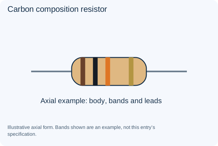
What it does
Uses a resistive bulk mixture rather than a deposited film. Found in many historical receivers and some specialized applications.
Example
An older radio bias network.
Important distinction
Age, noise and stability must be assessed; appearance is not a measurement.
Specifications to read
Resistance (Ω), tolerance (%), power (W), working voltage, temperature coefficient and pulse behavior.
A rating is a limit or condition, not a guarantee of suitability. Use the manufacturer's data sheet for the exact component and the equipment's schematic for its intended role.
Carbon film resistorResistors
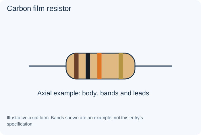
What it does
Uses a carbon film as the resistive element. It is a fixed-resistor construction rather than a separate circuit function.
Example
A general-purpose bias resistor.
Important distinction
Select by the required specifications rather than color or size alone.
Specifications to read
Resistance (Ω), tolerance (%), power (W), working voltage, temperature coefficient and pulse behavior.
A rating is a limit or condition, not a guarantee of suitability. Use the manufacturer's data sheet for the exact component and the equipment's schematic for its intended role.
Ceramic capacitorCapacitors
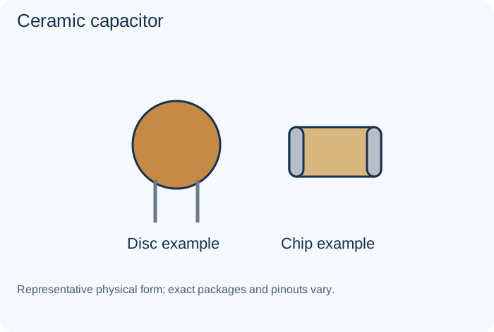
What it does
Uses ceramic dielectric. Different dielectric classes have different stability and operating behavior.
Example
High-frequency bypassing or a timing network.
Important distinction
Do not assume every ceramic retains its nominal capacitance under all conditions.
Specifications to read
Capacitance (F), tolerance, voltage, polarity, dielectric, ESR, leakage, ripple capability and temperature conditions.
A rating is a limit or condition, not a guarantee of suitability. Use the manufacturer's data sheet for the exact component and the equipment's schematic for its intended role.
Ceramic resonatorClocks and Resonators
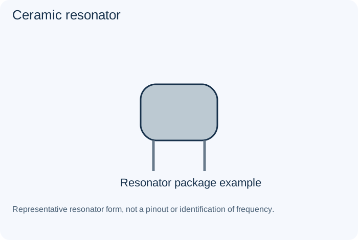
What it does
A resonant component used to establish timing in an appropriate circuit.
Example
An embedded controller clock.
Important distinction
Accuracy and circuit requirements differ from a quartz implementation.
Specifications to read
Frequency, accuracy, drive/load, supply where applicable, output format and oscillator compatibility.
A rating is a limit or condition, not a guarantee of suitability. Use the manufacturer's data sheet for the exact component and the equipment's schematic for its intended role.
ChokeInductors and Transformers
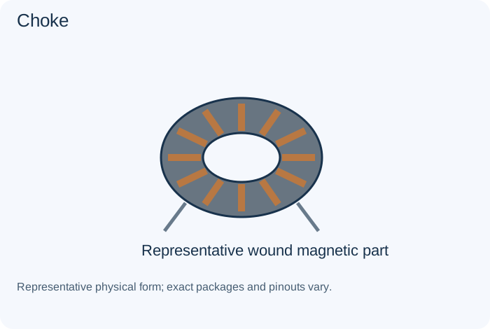
What it does
An inductor used primarily to impede unwanted varying current or interference.
Example
Supply filtering in suitable equipment.
Important distinction
Choose according to the current, frequency and circuit role.
Specifications to read
Inductance, winding resistance, current, saturation, frequency, losses, coupling and required insulation.
A rating is a limit or condition, not a guarantee of suitability. Use the manufacturer's data sheet for the exact component and the equipment's schematic for its intended role.
Clock oscillator moduleClocks and Resonators
What it does
Combines timing circuitry in a module that supplies a specified clock output.
Example
A digital timing source.
Important distinction
Supply, output logic and enable behavior must match the load.
Specifications to read
Frequency, accuracy, drive/load, supply where applicable, output format and oscillator compatibility.
A rating is a limit or condition, not a guarantee of suitability. Use the manufacturer's data sheet for the exact component and the equipment's schematic for its intended role.
Common-mode chokeInductors and Transformers
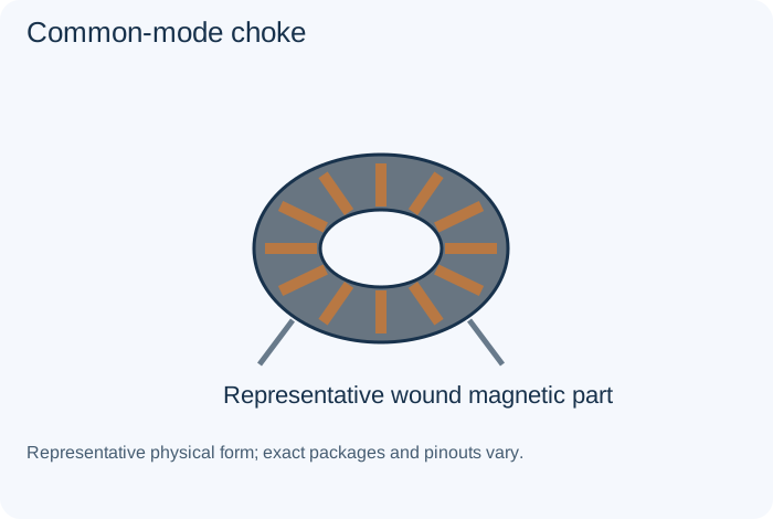
What it does
Uses coupled windings to impede common-mode disturbances while supporting the intended signal or power path.
Example
An interface or input filter.
Important distinction
Its differential and common-mode behavior are different.
Specifications to read
Inductance, winding resistance, current, saturation, frequency, losses, coupling and required insulation.
A rating is a limit or condition, not a guarantee of suitability. Use the manufacturer's data sheet for the exact component and the equipment's schematic for its intended role.
ComparatorIntegrated Circuits
What it does
Compares signals and changes its output according to their relationship under specified conditions.
Example
A threshold detector.
Important distinction
Output type and hysteresis requirements differ from those of an op-amp circuit.
Specifications to read
Exact part/revision, pinout, supply, input/output ranges, timing, interface, thermal limits and required surrounding parts.
A rating is a limit or condition, not a guarantee of suitability. Use the manufacturer's data sheet for the exact component and the equipment's schematic for its intended role.
Comparator and Schmitt triggerCommon Circuits
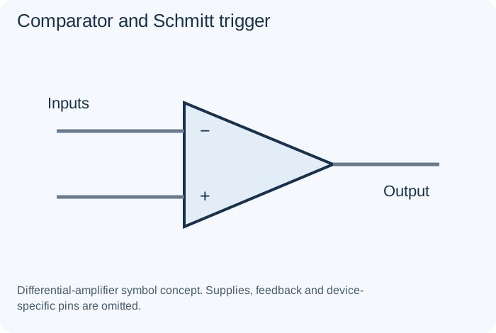
What it does
Threshold circuitry produces state changes; a Schmitt arrangement adds hysteresis.
Example
A noisy input threshold detector.
Important distinction
Hysteresis and output interface must match the required behavior.
Specifications to read
Intended function, source/load, operating range, component limits, response, stability, protection and layout.
A rating is a limit or condition, not a guarantee of suitability. Use the manufacturer's data sheet for the exact component and the equipment's schematic for its intended role.
Connector, terminal and headerSwitches, Relays and Connectors
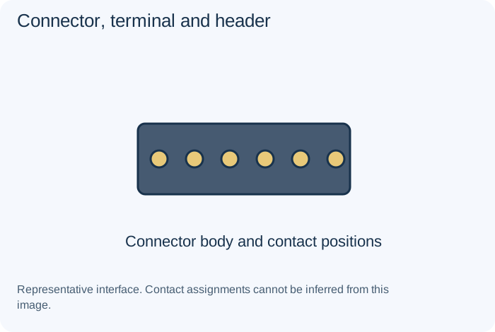
What it does
Provides a removable electrical or mechanical interface.
Example
Board-to-board, wire-to-board or panel connections.
Important distinction
Pin assignment, keying and current rating must be confirmed; a fitting plug is not proof of compatibility.
Specifications to read
Contact or interface assignment, voltage/current, load type, keying, mechanical requirements and insulation.
A rating is a limit or condition, not a guarantee of suitability. Use the manufacturer's data sheet for the exact component and the equipment's schematic for its intended role.
CRTVacuum Tubes and Historical Parts
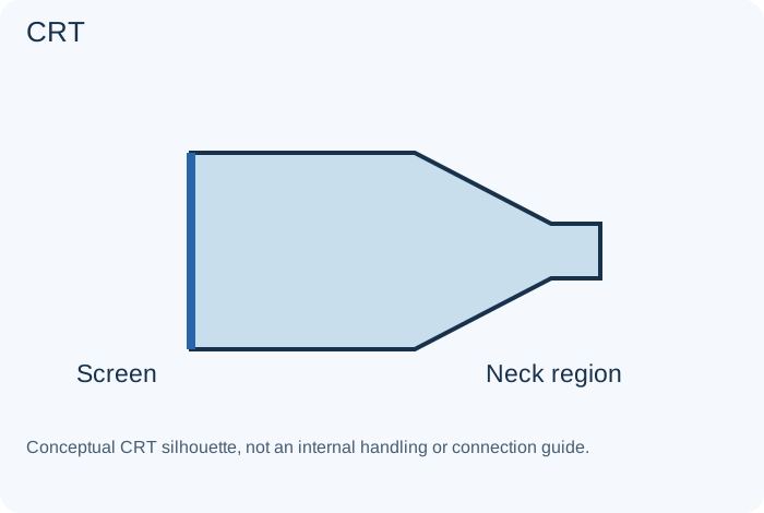
What it does
An electron-beam display with a phosphor screen and associated control/deflection systems.
Example
A television or arcade monitor.
Important distinction
Stored high voltage and fragile evacuated glass require qualified model-specific handling.
Specifications to read
Exact type, pinout, heater and operating requirements, circuit role and model-specific service data.
A rating is a limit or condition, not a guarantee of suitability. Use the manufacturer's data sheet for the exact component and the equipment's schematic for its intended role.
Current-sense resistorResistors
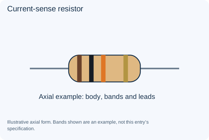
What it does
Produces a small voltage drop related to current, allowing a circuit to estimate or regulate that current.
Example
An amplifier or converter current-monitoring path.
Important distinction
Connection resistance and thermal behavior can affect accuracy.
Specifications to read
Resistance (Ω), tolerance (%), power (W), working voltage, temperature coefficient and pulse behavior.
A rating is a limit or condition, not a guarantee of suitability. Use the manufacturer's data sheet for the exact component and the equipment's schematic for its intended role.
Current source and current mirrorCommon Circuits
What it does
A current source seeks a controlled current; a mirror transfers a current relationship through suitable active devices.
Example
Biasing or analog processing.
Important distinction
Compliance voltage and device matching limit ideal behavior.
Specifications to read
Intended function, source/load, operating range, component limits, response, stability, protection and layout.
A rating is a limit or condition, not a guarantee of suitability. Use the manufacturer's data sheet for the exact component and the equipment's schematic for its intended role.
Darlington transistorTransistors and Controlled Switches
What it does
Combines bipolar stages to provide a particular high-gain arrangement.
Example
A documented driver circuit.
Important distinction
Its voltage-drop and switching behavior differ from a single transistor.
Specifications to read
Pinout, drive conditions, voltage/current, losses, temperature and safe operating limits.
A rating is a limit or condition, not a guarantee of suitability. Use the manufacturer's data sheet for the exact component and the equipment's schematic for its intended role.
DC adapter and isolated supplyPower Sources and Outputs
What it does
Converts an available source into a specified output; some supplies provide certified isolation.
Example
A documented low-voltage trainer.
Important distinction
Output voltage, polarity, current and safety properties must be verified separately.
Specifications to read
Source/load compatibility, polarity, current, chemistry where relevant, interface, mechanical and thermal conditions.
A rating is a limit or condition, not a guarantee of suitability. Use the manufacturer's data sheet for the exact component and the equipment's schematic for its intended role.
Debounce networkCommon Circuits
What it does
Helps distinguish intended switch actions from rapid contact transitions.
Example
A digital control input.
Important distinction
Analog filtering and software approaches have different timing implications.
Specifications to read
Intended function, source/load, operating range, component limits, response, stability, protection and layout.
A rating is a limit or condition, not a guarantee of suitability. Use the manufacturer's data sheet for the exact component and the equipment's schematic for its intended role.
Decoupling and bulk storage networkCommon Circuits
What it does
Provides local energy and impedance control for a supply under changing demand.
Example
A digital or amplifier supply.
Important distinction
Placement and frequency behavior matter; one large capacitor is not universally sufficient.
Specifications to read
Intended function, source/load, operating range, component limits, response, stability, protection and layout.
A rating is a limit or condition, not a guarantee of suitability. Use the manufacturer's data sheet for the exact component and the equipment's schematic for its intended role.
Depletion-mode FETTransistors and Controlled Switches
What it does
A field-effect device with a conducting channel at zero gate-to-source bias under its defined conditions.
Example
A documented current or switching circuit.
Important distinction
It cannot be substituted casually for an enhancement-mode device.
Specifications to read
Pinout, drive conditions, voltage/current, losses, temperature and safe operating limits.
A rating is a limit or condition, not a guarantee of suitability. Use the manufacturer's data sheet for the exact component and the equipment's schematic for its intended role.
Digital multimeterTest Equipment
What it does
Measures supported electrical quantities with modes and input limits defined by its manufacturer.
Example
A documented voltage or resistance check.
Important distinction
Current mode is not connected like voltage mode; wrong connections can create a short.
Specifications to read
Supported modes, input limits, probes, reference/ground, bandwidth or test conditions and appropriate training.
A rating is a limit or condition, not a guarantee of suitability. Use the manufacturer's data sheet for the exact component and the equipment's schematic for its intended role.
DPDT and rotary switchSwitches, Relays and Connectors
What it does
A DPDT provides two coordinated changeover poles; rotary switches can select among multiple positions.
Example
Polarity selection in an approved trainer or source selection.
Important distinction
Mechanical position alone does not establish the internal contact arrangement.
Specifications to read
Contact or interface assignment, voltage/current, load type, keying, mechanical requirements and insulation.
A rating is a limit or condition, not a guarantee of suitability. Use the manufacturer's data sheet for the exact component and the equipment's schematic for its intended role.
DSPIntegrated Circuits
What it does
A processing device or function optimized for digital signal operations.
Example
Audio filtering or communications processing.
Important distinction
Its code, data format and interfaces are part of the implemented system.
Specifications to read
Exact part/revision, pinout, supply, input/output ranges, timing, interface, thermal limits and required surrounding parts.
A rating is a limit or condition, not a guarantee of suitability. Use the manufacturer's data sheet for the exact component and the equipment's schematic for its intended role.
EEPROM, flash and RAM distinctionsIntegrated Circuits
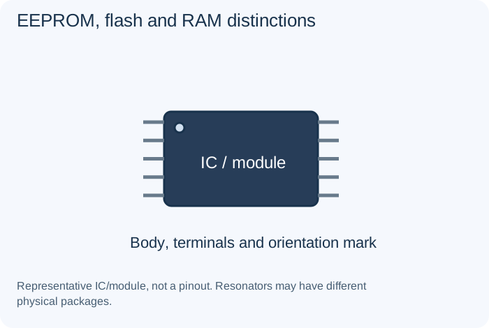
What it does
EEPROM and flash are nonvolatile technologies; RAM provides working storage in applicable designs.
Example
Configuration, program or working data.
Important distinction
Interface, organization and write behavior are technology-specific.
Specifications to read
Exact part/revision, pinout, supply, input/output ranges, timing, interface, thermal limits and required surrounding parts.
A rating is a limit or condition, not a guarantee of suitability. Use the manufacturer's data sheet for the exact component and the equipment's schematic for its intended role.
Electromechanical relaySwitches, Relays and Connectors
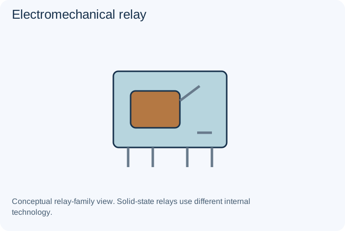
What it does
Uses a coil-operated mechanism to control contacts.
Example
Switching a separate load from a control circuit.
Important distinction
Coil and contact specifications are independent requirements.
Specifications to read
Contact or interface assignment, voltage/current, load type, keying, mechanical requirements and insulation.
A rating is a limit or condition, not a guarantee of suitability. Use the manufacturer's data sheet for the exact component and the equipment's schematic for its intended role.
Encoder and potentiometric sensorSensors and Transducers
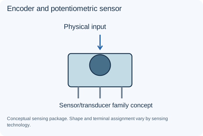
What it does
An encoder represents movement through encoded outputs; a potentiometric sensor represents position through a resistive relationship.
Example
A control knob or position measurement.
Important distinction
Incremental, absolute and analog interfaces should not be confused.
Specifications to read
Measured quantity/reference, range, accuracy, response, supply/bias, interface, calibration and environment.
A rating is a limit or condition, not a guarantee of suitability. Use the manufacturer's data sheet for the exact component and the equipment's schematic for its intended role.
ESR meterTest Equipment
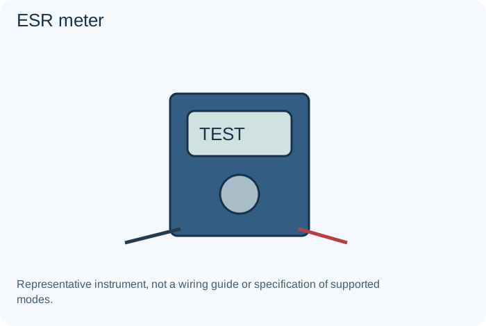
What it does
Measures an equivalent series-resistance characteristic under its stated conditions.
Example
Assessment of a suitable capacitor.
Important distinction
An ESR result alone does not establish leakage, capacitance or every failure mode.
Specifications to read
Supported modes, input limits, probes, reference/ground, bandwidth or test conditions and appropriate training.
A rating is a limit or condition, not a guarantee of suitability. Use the manufacturer's data sheet for the exact component and the equipment's schematic for its intended role.
Fast-recovery diodeDiodes

What it does
A rectifying device selected for suitable recovery behavior when switching between conduction conditions.
Example
A switching converter.
Important distinction
Recovery, thermal and voltage/current requirements must all suit the design.
Specifications to read
Forward/reverse voltage behavior, current, dissipation, recovery or response and application-specific limits.
A rating is a limit or condition, not a guarantee of suitability. Use the manufacturer's data sheet for the exact component and the equipment's schematic for its intended role.
Ferrite beadInductors and Transformers
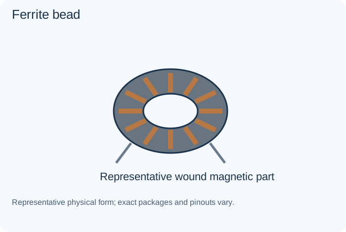
What it does
Provides frequency-dependent impedance useful for reducing selected interference.
Example
A noisy supply or signal interface.
Important distinction
It is not a general-purpose replacement for a power inductor.
Specifications to read
Inductance, winding resistance, current, saturation, frequency, losses, coupling and required insulation.
A rating is a limit or condition, not a guarantee of suitability. Use the manufacturer's data sheet for the exact component and the equipment's schematic for its intended role.
Film capacitorCapacitors
What it does
Uses a plastic-film dielectric, with different materials and electrode constructions available.
Example
Signal coupling or a specified pulse circuit.
Important distinction
Film type, pulse capability and ratings can matter as much as capacitance.
Specifications to read
Capacitance (F), tolerance, voltage, polarity, dielectric, ESR, leakage, ripple capability and temperature conditions.
A rating is a limit or condition, not a guarantee of suitability. Use the manufacturer's data sheet for the exact component and the equipment's schematic for its intended role.
Fixed resistorResistors
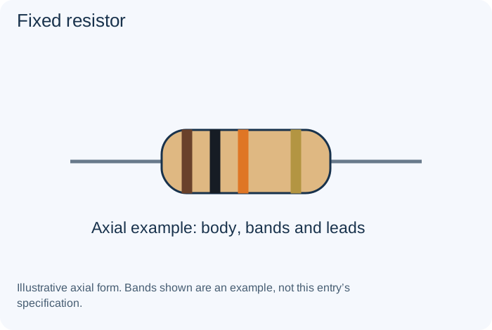
What it does
Opposes current flow and dissipates electrical energy as heat. Resistance is measured in ohms; a circuit also depends on tolerance and operating conditions.
Example
Limiting current in a low-voltage indicator circuit.
Important distinction
A resistance value alone does not specify power, voltage or pulse suitability.
Specifications to read
Resistance (Ω), tolerance (%), power (W), working voltage, temperature coefficient and pulse behavior.
A rating is a limit or condition, not a guarantee of suitability. Use the manufacturer's data sheet for the exact component and the equipment's schematic for its intended role.
Flyback converterCommon Circuits
What it does
Uses a coupled magnetic component and controlled energy-transfer intervals in a suitable switching design.
Example
An isolated supply design.
Important distinction
Isolation and regulation are design properties, not consequences of the name alone.
Specifications to read
Intended function, source/load, operating range, component limits, response, stability, protection and layout.
A rating is a limit or condition, not a guarantee of suitability. Use the manufacturer's data sheet for the exact component and the equipment's schematic for its intended role.
Flyback transformerInductors and Transformers
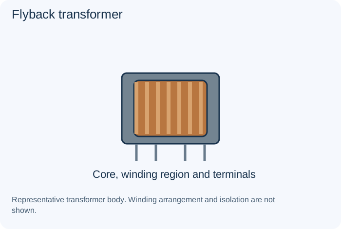
What it does
A coupled magnetic component used in a flyback energy-transfer arrangement; older CRT implementations have specialized high-voltage functions.
Example
An isolated converter or documented CRT system.
Important distinction
Ordinary transformer assumptions and casual meter probes are unsuitable for high-voltage CRT work.
Specifications to read
Inductance, winding resistance, current, saturation, frequency, losses, coupling and required insulation.
A rating is a limit or condition, not a guarantee of suitability. Use the manufacturer's data sheet for the exact component and the equipment's schematic for its intended role.
FPGA and programmable logicIntegrated Circuits
What it does
Devices whose digital logic arrangement is configured for an application.
Example
A specialized controller or signal processor.
Important distinction
Configuration and compatible electrical interfaces are required; package fit is insufficient.
Specifications to read
Exact part/revision, pinout, supply, input/output ranges, timing, interface, thermal limits and required surrounding parts.
A rating is a limit or condition, not a guarantee of suitability. Use the manufacturer's data sheet for the exact component and the equipment's schematic for its intended role.
FuseProtection Parts
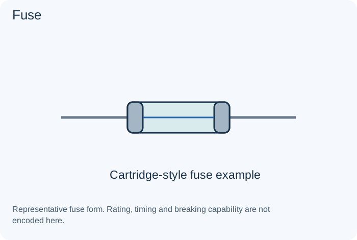
What it does
Interrupts a circuit according to its specified time-current and breaking behavior.
Example
A protected power input.
Important distinction
Never increase its rating to hide recurring failure; current rating is not its only specification.
Specifications to read
Approved function, ratings, fault behavior, breaking/energy capability and required protection coordination.
A rating is a limit or condition, not a guarantee of suitability. Use the manufacturer's data sheet for the exact component and the equipment's schematic for its intended role.
Fusible resistorResistors
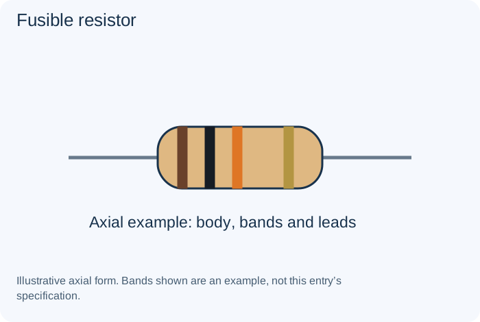
What it does
Provides resistance with a specified protective opening behavior under applicable conditions.
Example
A documented protective input network.
Important distinction
An ordinary resistor is not an equivalent protective replacement.
Specifications to read
Resistance (Ω), tolerance (%), power (W), working voltage, temperature coefficient and pulse behavior.
A rating is a limit or condition, not a guarantee of suitability. Use the manufacturer's data sheet for the exact component and the equipment's schematic for its intended role.
Gas discharge tubeProtection Parts
What it does
Uses controlled gas breakdown to divert certain transient events in a designed protection path.
Example
A communication or surge interface.
Important distinction
Its operation differs from a low-voltage diode clamp.
Specifications to read
Approved function, ratings, fault behavior, breaking/energy capability and required protection coordination.
A rating is a limit or condition, not a guarantee of suitability. Use the manufacturer's data sheet for the exact component and the equipment's schematic for its intended role.
Half-wave and full-wave rectifierCommon Circuits
What it does
Converts alternating input into unidirectional portions or pulses using an appropriate arrangement.
Example
A documented supply stage.
Important distinction
Rectification is not the same as regulation or isolation.
Specifications to read
Intended function, source/load, operating range, component limits, response, stability, protection and layout.
A rating is a limit or condition, not a guarantee of suitability. Use the manufacturer's data sheet for the exact component and the equipment's schematic for its intended role.
Hall-effect sensorSensors and Transducers
What it does
Measures or detects magnetic influence through a semiconductor sensing principle.
Example
Position, speed or current sensing.
Important distinction
Analog, switching and digital-output versions require different interfaces.
Specifications to read
Measured quantity/reference, range, accuracy, response, supply/bias, interface, calibration and environment.
A rating is a limit or condition, not a guarantee of suitability. Use the manufacturer's data sheet for the exact component and the equipment's schematic for its intended role.
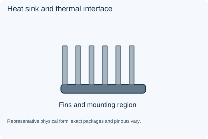
Heat sink and thermal interfacePower Sources and Outputs
What it does
Helps transfer dissipated heat from a component to its surroundings.
Example
A power amplifier or regulator.
Important distinction
Mounting, insulation and thermal resistance are part of the design, not cosmetic details.
Specifications to read
Source/load compatibility, polarity, current, chemistry where relevant, interface, mechanical and thermal conditions.
A rating is a limit or condition, not a guarantee of suitability. Use the manufacturer's data sheet for the exact component and the equipment's schematic for its intended role.
High-pass filterCommon Circuits
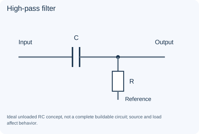
What it does
Reduces lower-frequency content relative to higher-frequency content.
Example
An AC-coupled signal path.
Important distinction
Its behavior depends on source and load impedances.
Specifications to read
Intended function, source/load, operating range, component limits, response, stability, protection and layout.
A rating is a limit or condition, not a guarantee of suitability. Use the manufacturer's data sheet for the exact component and the equipment's schematic for its intended role.
Humidity sensorSensors and Transducers
What it does
Produces an electrical response related to moisture in its specified environment.
Example
Environmental measurement.
Important distinction
Temperature, contamination and calibration can influence results.
Specifications to read
Measured quantity/reference, range, accuracy, response, supply/bias, interface, calibration and environment.
A rating is a limit or condition, not a guarantee of suitability. Use the manufacturer's data sheet for the exact component and the equipment's schematic for its intended role.
IGBTTransistors and Controlled Switches
What it does
Combines an insulated-gate input with bipolar-related conduction behavior for suitable power applications.
Example
A qualified motor-drive or power-converter design.
Important distinction
Switching loss, safe operating limits and gate drive need coordinated design.
Specifications to read
Pinout, drive conditions, voltage/current, losses, temperature and safe operating limits.
A rating is a limit or condition, not a guarantee of suitability. Use the manufacturer's data sheet for the exact component and the equipment's schematic for its intended role.
Impedance-matching networkCommon Circuits
What it does
Transforms or coordinates the source/load relationship over an intended range.
Example
An RF or audio interface.
Important distinction
Matching depends on frequency and application; resistance alone may be insufficient.
Specifications to read
Intended function, source/load, operating range, component limits, response, stability, protection and layout.
A rating is a limit or condition, not a guarantee of suitability. Use the manufacturer's data sheet for the exact component and the equipment's schematic for its intended role.
InductorInductors and Transformers
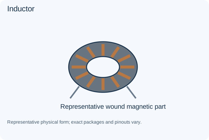
What it does
Stores energy in a magnetic field and opposes changes in current. Its behavior also includes winding resistance and parasitic effects.
Example
A switching converter or filter.
Important distinction
Inductance alone does not specify saturation, heating or frequency behavior.
Specifications to read
Inductance, winding resistance, current, saturation, frequency, losses, coupling and required insulation.
A rating is a limit or condition, not a guarantee of suitability. Use the manufacturer's data sheet for the exact component and the equipment's schematic for its intended role.
Infrared LED and laser diodeDiodes
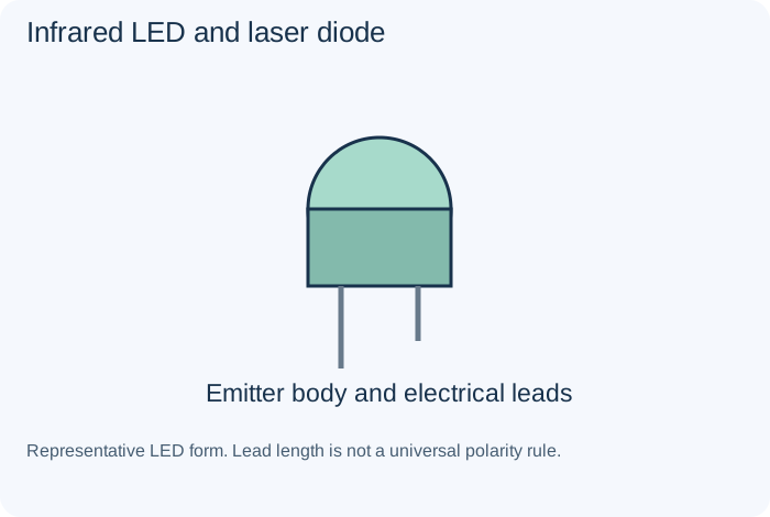
What it does
Emitters selected for infrared signaling or coherent-light applications, respectively.
Example
An optical remote or qualified optical assembly.
Important distinction
They are distinct devices; laser systems require their specified optical precautions.
Specifications to read
Forward/reverse voltage behavior, current, dissipation, recovery or response and application-specific limits.
A rating is a limit or condition, not a guarantee of suitability. Use the manufacturer's data sheet for the exact component and the equipment's schematic for its intended role.
Inverting and non-inverting amplifierCommon Circuits
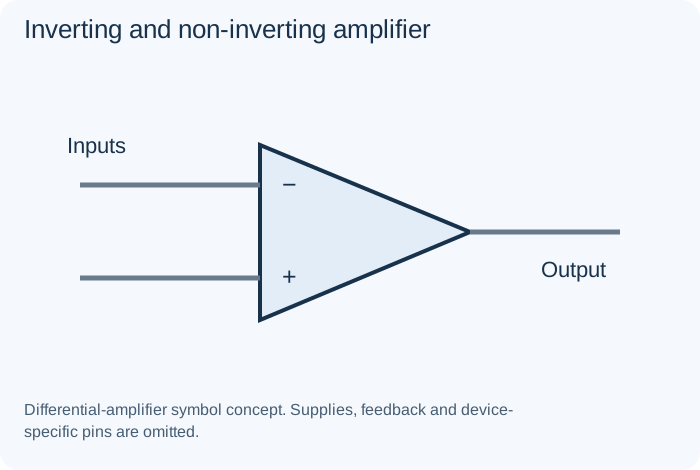
What it does
Feedback arrangements establish an intended gain and polarity relationship.
Example
An analog signal-conditioning stage.
Important distinction
Real op-amp input/output ranges and stability limit the ideal equations.
Specifications to read
Intended function, source/load, operating range, component limits, response, stability, protection and layout.
A rating is a limit or condition, not a guarantee of suitability. Use the manufacturer's data sheet for the exact component and the equipment's schematic for its intended role.
JFETTransistors and Controlled Switches
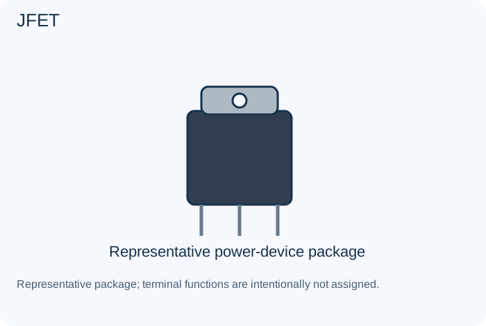
What it does
A junction field-effect transistor whose channel behavior is controlled by its gate junction conditions.
Example
An input stage or analog switching function.
Important distinction
Pinouts and operating modes are part-specific.
Specifications to read
Pinout, drive conditions, voltage/current, losses, temperature and safe operating limits.
A rating is a limit or condition, not a guarantee of suitability. Use the manufacturer's data sheet for the exact component and the equipment's schematic for its intended role.
LCD and OLED displayPower Sources and Outputs
What it does
LCD modulates light through a display arrangement; OLED emits light from its active display elements.
Example
A receiver interface or instrument.
Important distinction
Driver, interface, voltage and panel revision determine compatibility.
Specifications to read
Source/load compatibility, polarity, current, chemistry where relevant, interface, mechanical and thermal conditions.
A rating is a limit or condition, not a guarantee of suitability. Use the manufacturer's data sheet for the exact component and the equipment's schematic for its intended role.
LCR meterTest Equipment
What it does
Measures resistance, capacitance or inductance under stated test conditions.
Example
A component assessment record.
Important distinction
In-circuit paths and test frequency can affect interpretation.
Specifications to read
Supported modes, input limits, probes, reference/ground, bandwidth or test conditions and appropriate training.
A rating is a limit or condition, not a guarantee of suitability. Use the manufacturer's data sheet for the exact component and the equipment's schematic for its intended role.
LEDDiodes
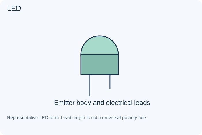
What it does
Emits light when operated with an appropriate forward current and thermal design.
Example
A status indicator or illumination assembly.
Important distinction
An LED requires a suitable current-control circuit; color alone does not determine its limits.
Specifications to read
Forward/reverse voltage behavior, current, dissipation, recovery or response and application-specific limits.
A rating is a limit or condition, not a guarantee of suitability. Use the manufacturer's data sheet for the exact component and the equipment's schematic for its intended role.
Linear-regulated supplyCommon Circuits
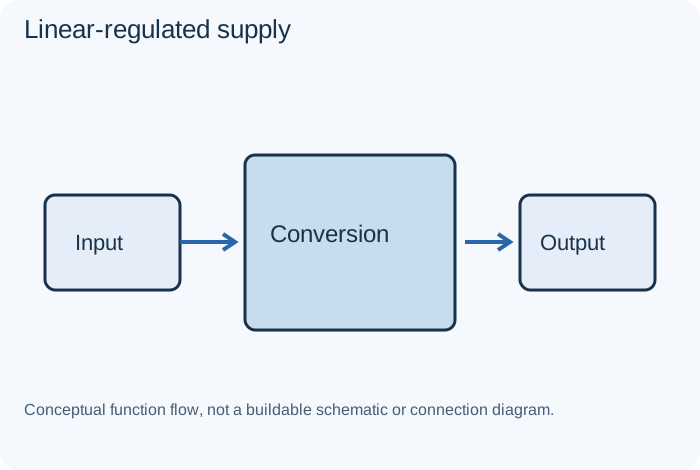
What it does
Uses a linear control/pass arrangement to maintain an intended output within its conditions.
Example
An analog supply rail.
Important distinction
Input-output difference and current create heat that must be managed.
Specifications to read
Intended function, source/load, operating range, component limits, response, stability, protection and layout.
A rating is a limit or condition, not a guarantee of suitability. Use the manufacturer's data sheet for the exact component and the equipment's schematic for its intended role.
Linear regulator and LDOIntegrated Circuits
What it does
Controls an output supply using a linear pass arrangement. An LDO can operate with a relatively small specified input-output difference.
Example
A low-noise supply rail.
Important distinction
Dropout, heat, load and capacitor requirements still apply.
Specifications to read
Exact part/revision, pinout, supply, input/output ranges, timing, interface, thermal limits and required surrounding parts.
A rating is a limit or condition, not a guarantee of suitability. Use the manufacturer's data sheet for the exact component and the equipment's schematic for its intended role.
Logic gateIntegrated Circuits
What it does
Implements a Boolean function such as AND, OR, NOT, NAND or XOR.
Example
Combining digital control conditions.
Important distinction
Logic voltage families and input thresholds must be compatible.
Specifications to read
Exact part/revision, pinout, supply, input/output ranges, timing, interface, thermal limits and required surrounding parts.
A rating is a limit or condition, not a guarantee of suitability. Use the manufacturer's data sheet for the exact component and the equipment's schematic for its intended role.
Logic latch, flip-flop and counterCommon Circuits
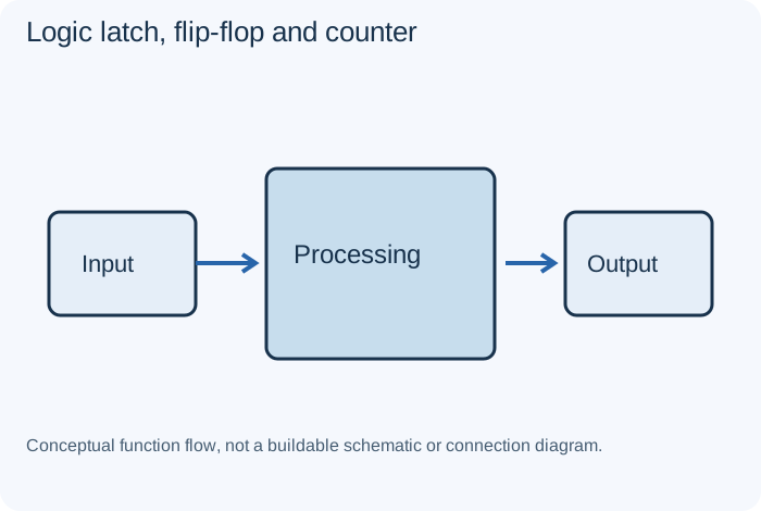
What it does
Digital arrangements store state or progress through a defined sequence.
Example
Control or timing logic.
Important distinction
Clocking, initialization and valid signal levels determine behavior.
Specifications to read
Intended function, source/load, operating range, component limits, response, stability, protection and layout.
A rating is a limit or condition, not a guarantee of suitability. Use the manufacturer's data sheet for the exact component and the equipment's schematic for its intended role.
Low-pass filterCommon Circuits
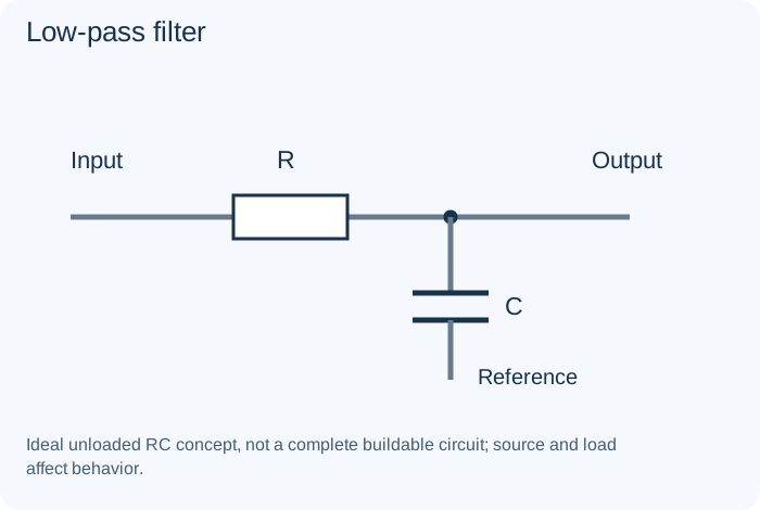
What it does
Reduces higher-frequency content relative to lower-frequency content according to its response.
Example
Reducing suitable measurement noise.
Important distinction
Cutoff is not an abrupt wall; order and loading matter.
Specifications to read
Intended function, source/load, operating range, component limits, response, stability, protection and layout.
A rating is a limit or condition, not a guarantee of suitability. Use the manufacturer's data sheet for the exact component and the equipment's schematic for its intended role.
Memory ICIntegrated Circuits
What it does
Stores program, working or nonvolatile information, depending on technology.
Example
RAM, flash or an EEPROM configuration store.
Important distinction
Package fit does not establish interface, voltage or data compatibility.
Specifications to read
Exact part/revision, pinout, supply, input/output ranges, timing, interface, thermal limits and required surrounding parts.
A rating is a limit or condition, not a guarantee of suitability. Use the manufacturer's data sheet for the exact component and the equipment's schematic for its intended role.
Metal-foil resistorResistors
What it does
A precision resistor construction selected for particular stability and accuracy requirements.
Example
A measurement reference network.
Important distinction
The required environment and mounting conditions still matter.
Specifications to read
Resistance (Ω), tolerance (%), power (W), working voltage, temperature coefficient and pulse behavior.
A rating is a limit or condition, not a guarantee of suitability. Use the manufacturer's data sheet for the exact component and the equipment's schematic for its intended role.
Metal film resistorResistors
What it does
Uses a metal resistive film. Available with characteristics suited to many precision and low-noise applications.
Example
A measurement divider.
Important distinction
Its actual tolerance and temperature coefficient come from the specific part.
Specifications to read
Resistance (Ω), tolerance (%), power (W), working voltage, temperature coefficient and pulse behavior.
A rating is a limit or condition, not a guarantee of suitability. Use the manufacturer's data sheet for the exact component and the equipment's schematic for its intended role.
Mica and paper capacitorsCapacitors
What it does
Mica and historical paper dielectric parts are distinct technologies. Identification is important when studying old equipment.
Example
A tuned receiver circuit or historical coupling network.
Important distinction
Do not treat different dielectrics as one replacement family.
Specifications to read
Capacitance (F), tolerance, voltage, polarity, dielectric, ESR, leakage, ripple capability and temperature conditions.
A rating is a limit or condition, not a guarantee of suitability. Use the manufacturer's data sheet for the exact component and the equipment's schematic for its intended role.
MicrocontrollerIntegrated Circuits
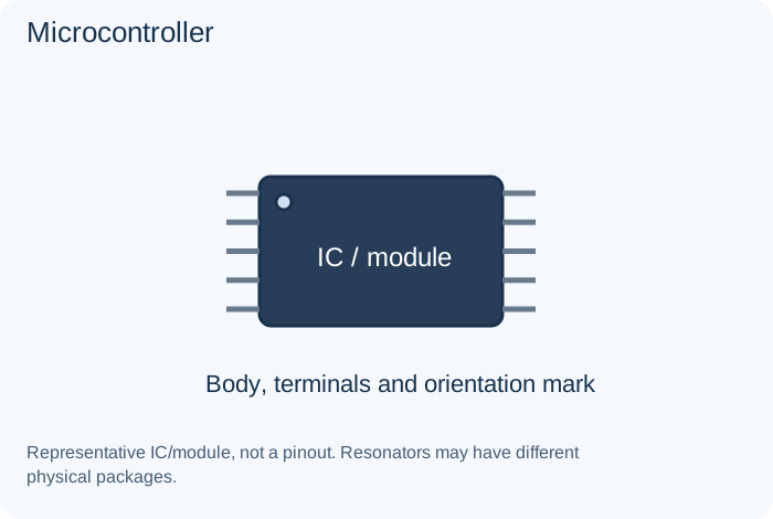
What it does
Combines processing, memory and peripherals for programmed control.
Example
A display controller or embedded instrument.
Important distinction
Firmware and peripheral configuration are part of the system behavior.
Specifications to read
Exact part/revision, pinout, supply, input/output ranges, timing, interface, thermal limits and required surrounding parts.
A rating is a limit or condition, not a guarantee of suitability. Use the manufacturer's data sheet for the exact component and the equipment's schematic for its intended role.
MicrophoneSensors and Transducers
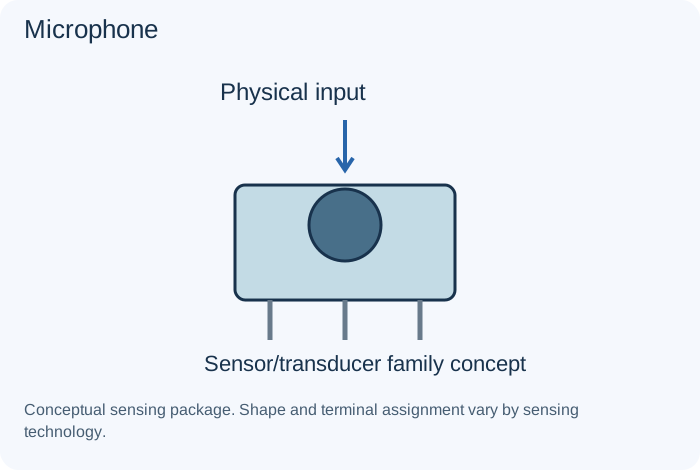
What it does
Converts sound-related motion or pressure into an electrical signal using an appropriate transducer technology.
Example
A car-radio call input or recording system.
Important distinction
Dynamic, electret and digital microphones are not interchangeable without suitable circuitry.
Specifications to read
Measured quantity/reference, range, accuracy, response, supply/bias, interface, calibration and environment.
A rating is a limit or condition, not a guarantee of suitability. Use the manufacturer's data sheet for the exact component and the equipment's schematic for its intended role.
Motor and solenoidPower Sources and Outputs
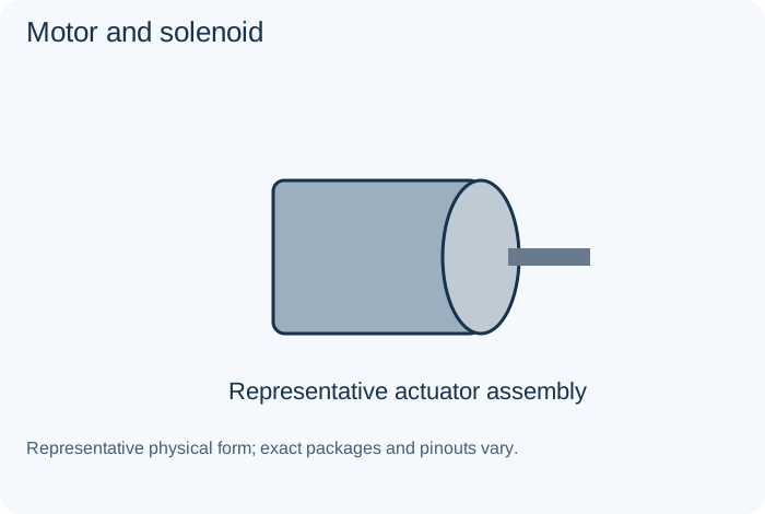
What it does
A motor produces rotational or other sustained motion; a solenoid provides a magnetic actuator function.
Example
A cassette mechanism or controlled latch.
Important distinction
Stall current, inductive behavior and mechanical load affect the driver.
Specifications to read
Source/load compatibility, polarity, current, chemistry where relevant, interface, mechanical and thermal conditions.
A rating is a limit or condition, not a guarantee of suitability. Use the manufacturer's data sheet for the exact component and the equipment's schematic for its intended role.
MOV varistorProtection Parts
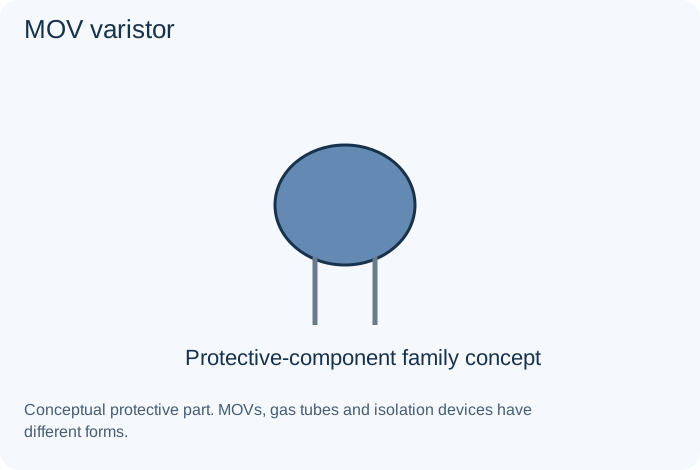
What it does
Provides voltage-dependent behavior useful for specified transient suppression.
Example
An approved surge-protection network.
Important distinction
Clamping, energy, aging and protection coordination matter.
Specifications to read
Approved function, ratings, fault behavior, breaking/energy capability and required protection coordination.
A rating is a limit or condition, not a guarantee of suitability. Use the manufacturer's data sheet for the exact component and the equipment's schematic for its intended role.
N-channel MOSFETTransistors and Controlled Switches
What it does
A field-effect device controlled by gate-to-source voltage in its intended operating arrangement.
Example
A power switch or converter.
Important distinction
Threshold voltage is not a promise of low resistance at that gate drive.
Specifications to read
Pinout, drive conditions, voltage/current, losses, temperature and safe operating limits.
A rating is a limit or condition, not a guarantee of suitability. Use the manufacturer's data sheet for the exact component and the equipment's schematic for its intended role.
NPN bipolar transistorTransistors and Controlled Switches
What it does
A bipolar transistor whose collector behavior depends on the base-emitter operating condition and the surrounding circuit.
Example
A signal amplifier or low-side switch.
Important distinction
Gain, pinout, voltage, current and thermal limits vary by part.
Specifications to read
Pinout, drive conditions, voltage/current, losses, temperature and safe operating limits.
A rating is a limit or condition, not a guarantee of suitability. Use the manufacturer's data sheet for the exact component and the equipment's schematic for its intended role.
NTC thermistorSensors and Transducers
What it does
A temperature-dependent resistor whose resistance generally decreases as temperature rises in its specified range.
Example
Temperature sensing or selected inrush arrangements.
Important distinction
A sensing thermistor and an inrush limiter have different application requirements.
Specifications to read
Measured quantity/reference, range, accuracy, response, supply/bias, interface, calibration and environment.
A rating is a limit or condition, not a guarantee of suitability. Use the manufacturer's data sheet for the exact component and the equipment's schematic for its intended role.
Operational amplifierIntegrated Circuits
What it does
An analog amplifier with differential inputs, commonly used with feedback to establish a controlled circuit function.
Example
A sensor buffer or active filter.
Important distinction
Input range, supply limits, stability and output capability constrain real devices.
Specifications to read
Exact part/revision, pinout, supply, input/output ranges, timing, interface, thermal limits and required surrounding parts.
A rating is a limit or condition, not a guarantee of suitability. Use the manufacturer's data sheet for the exact component and the equipment's schematic for its intended role.
Optocoupler and isolation barrierProtection Parts
What it does
An optocoupler transfers information through light within its specified isolation arrangement. Other technologies also implement isolation barriers.
Example
An isolated feedback or interface path.
Important distinction
Isolation voltage alone is not a complete safety assessment of the installed system.
Specifications to read
Approved function, ratings, fault behavior, breaking/energy capability and required protection coordination.
A rating is a limit or condition, not a guarantee of suitability. Use the manufacturer's data sheet for the exact component and the equipment's schematic for its intended role.
Oscillator and crystal clockCommon Circuits
What it does
Produces repeating signals; crystal-based systems use a resonator within an appropriate circuit.
Example
A timing reference.
Important distinction
A resonator alone is not a complete oscillator, and frequency depends on its specified conditions.
Specifications to read
Intended function, source/load, operating range, component limits, response, stability, protection and layout.
A rating is a limit or condition, not a guarantee of suitability. Use the manufacturer's data sheet for the exact component and the equipment's schematic for its intended role.
Oscilloscope and probesTest Equipment
What it does
Displays signal variation over time within its bandwidth and input limits.
Example
Studying a waveform on an approved trainer.
Important distinction
Probe ratings and grounding are critical; a scope ground is not a universal floating reference.
Specifications to read
Supported modes, input limits, probes, reference/ground, bandwidth or test conditions and appropriate training.
A rating is a limit or condition, not a guarantee of suitability. Use the manufacturer's data sheet for the exact component and the equipment's schematic for its intended role.
P-channel MOSFETTransistors and Controlled Switches
What it does
A complementary MOSFET useful in selected switching arrangements.
Example
A suitably designed high-side switch.
Important distinction
Gate polarity and drive limits must match the actual circuit.
Specifications to read
Pinout, drive conditions, voltage/current, losses, temperature and safe operating limits.
A rating is a limit or condition, not a guarantee of suitability. Use the manufacturer's data sheet for the exact component and the equipment's schematic for its intended role.
Parallel circuitCommon Circuits
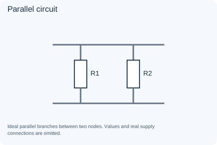
What it does
Connects branches across the same pair of nodes in the ideal model.
Example
Separate loads on a supply.
Important distinction
Shared voltage does not mean equal branch currents.
Specifications to read
Intended function, source/load, operating range, component limits, response, stability, protection and layout.
A rating is a limit or condition, not a guarantee of suitability. Use the manufacturer's data sheet for the exact component and the equipment's schematic for its intended role.
Peak detector and envelope detectorCommon Circuits
What it does
Detects signal peaks or the changing amplitude envelope with an appropriate network.
Example
A measurement or demodulation stage.
Important distinction
Time constants and loading determine which changes are followed.
Specifications to read
Intended function, source/load, operating range, component limits, response, stability, protection and layout.
A rating is a limit or condition, not a guarantee of suitability. Use the manufacturer's data sheet for the exact component and the equipment's schematic for its intended role.
PhotodiodeDiodes
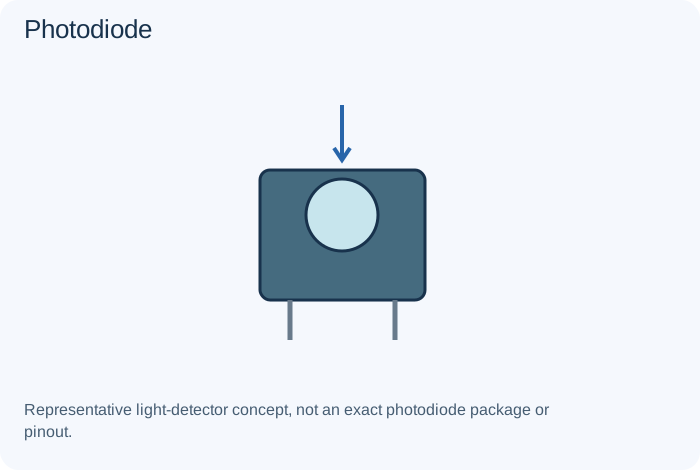
What it does
Converts incident light into an electrical response used by a sensing circuit.
Example
An optical receiver or light meter.
Important distinction
Its operating bias and signal conditioning depend on the application.
Specifications to read
Forward/reverse voltage behavior, current, dissipation, recovery or response and application-specific limits.
A rating is a limit or condition, not a guarantee of suitability. Use the manufacturer's data sheet for the exact component and the equipment's schematic for its intended role.
PhotoresistorSensors and Transducers
What it does
Changes resistance with incident light in its intended operating range.
Example
A light-dependent control.
Important distinction
Response speed, spectral behavior and application restrictions vary.
Specifications to read
Measured quantity/reference, range, accuracy, response, supply/bias, interface, calibration and environment.
A rating is a limit or condition, not a guarantee of suitability. Use the manufacturer's data sheet for the exact component and the equipment's schematic for its intended role.
PhototransistorTransistors and Controlled Switches
What it does
Produces a transistor-related electrical response to incident light.
Example
An optical detection circuit.
Important distinction
Light sensitivity, response speed and circuit bias affect interpretation.
Specifications to read
Pinout, drive conditions, voltage/current, losses, temperature and safe operating limits.
A rating is a limit or condition, not a guarantee of suitability. Use the manufacturer's data sheet for the exact component and the equipment's schematic for its intended role.
Piezoelectric elementSensors and Transducers
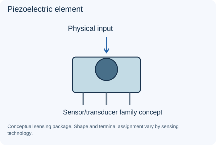
What it does
Converts mechanical stress and electrical excitation through piezoelectric behavior.
Example
A vibration sensor or buzzer.
Important distinction
Sensor and actuator applications need different drive and input conditions.
Specifications to read
Measured quantity/reference, range, accuracy, response, supply/bias, interface, calibration and environment.
A rating is a limit or condition, not a guarantee of suitability. Use the manufacturer's data sheet for the exact component and the equipment's schematic for its intended role.
PLLClocks and Resonators
What it does
A phase-locked-loop arrangement compares and controls phase/frequency behavior.
Example
A synthesizer or clock system.
Important distinction
Loop design, reference and lock conditions matter.
Specifications to read
Frequency, accuracy, drive/load, supply where applicable, output format and oscillator compatibility.
A rating is a limit or condition, not a guarantee of suitability. Use the manufacturer's data sheet for the exact component and the equipment's schematic for its intended role.
PNP bipolar transistorTransistors and Controlled Switches
What it does
A complementary bipolar transistor requiring appropriately reversed polarities relative to an NPN implementation.
Example
A suitable high-side or complementary stage.
Important distinction
It is not interchangeable with an NPN just because its package matches.
Specifications to read
Pinout, drive conditions, voltage/current, losses, temperature and safe operating limits.
A rating is a limit or condition, not a guarantee of suitability. Use the manufacturer's data sheet for the exact component and the equipment's schematic for its intended role.
Polyester film capacitorCapacitors
What it does
A film construction used in many suitable general signal applications.
Example
An applicable coupling network.
Important distinction
Do not assume it matches every polypropylene or historical capacitor requirement.
Specifications to read
Capacitance (F), tolerance, voltage, polarity, dielectric, ESR, leakage, ripple capability and temperature conditions.
A rating is a limit or condition, not a guarantee of suitability. Use the manufacturer's data sheet for the exact component and the equipment's schematic for its intended role.
Polymer capacitorCapacitors
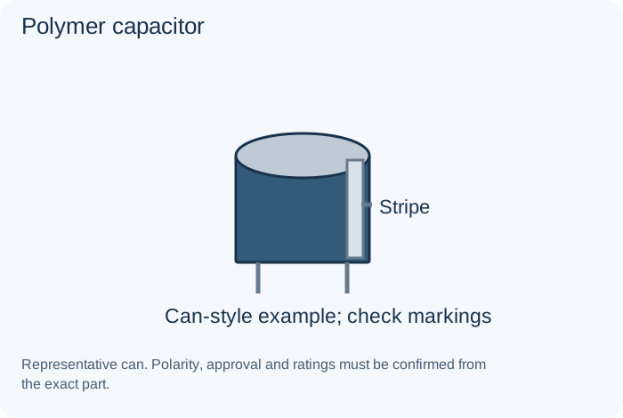
What it does
Uses a conductive polymer system in applicable capacitor constructions. Often selected for low-impedance supply applications.
Example
A regulator's specified output network.
Important distinction
Low ESR is not automatically compatible with every regulator design.
Specifications to read
Capacitance (F), tolerance, voltage, polarity, dielectric, ESR, leakage, ripple capability and temperature conditions.
A rating is a limit or condition, not a guarantee of suitability. Use the manufacturer's data sheet for the exact component and the equipment's schematic for its intended role.
Polypropylene film capacitorCapacitors
What it does
A film construction used in appropriate signal and pulse applications.
Example
A specified coupling or pulse network.
Important distinction
Pulse, AC and temperature suitability depend on the actual part.
Specifications to read
Capacitance (F), tolerance, voltage, polarity, dielectric, ESR, leakage, ripple capability and temperature conditions.
A rating is a limit or condition, not a guarantee of suitability. Use the manufacturer's data sheet for the exact component and the equipment's schematic for its intended role.
Potentiometer and rheostatResistors
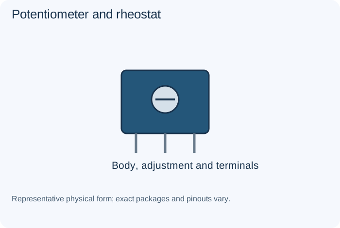
What it does
A potentiometer provides an adjustable tap on a resistance element. A rheostat connection uses variable resistance in a current path.
Example
A volume control or adjustable test load.
Important distinction
Taper, power rating and terminal arrangement are not interchangeable.
Specifications to read
Resistance (Ω), tolerance (%), power (W), working voltage, temperature coefficient and pulse behavior.
A rating is a limit or condition, not a guarantee of suitability. Use the manufacturer's data sheet for the exact component and the equipment's schematic for its intended role.
Pressure sensorSensors and Transducers
What it does
Converts a pressure-related physical condition into a specified electrical output.
Example
A monitored pneumatic system.
Important distinction
Absolute, gauge and differential types measure different references.
Specifications to read
Measured quantity/reference, range, accuracy, response, supply/bias, interface, calibration and environment.
A rating is a limit or condition, not a guarantee of suitability. Use the manufacturer's data sheet for the exact component and the equipment's schematic for its intended role.
Primary battery and rechargeable cellPower Sources and Outputs
What it does
A primary cell is intended for non-rechargeable service; rechargeable chemistry requires its specified charging method.
Example
A portable device supply.
Important distinction
Do not apply one chemistry's charger to another or treat every cell as interchangeable.
Specifications to read
Source/load compatibility, polarity, current, chemistry where relevant, interface, mechanical and thermal conditions.
A rating is a limit or condition, not a guarantee of suitability. Use the manufacturer's data sheet for the exact component and the equipment's schematic for its intended role.
PTC thermistorSensors and Transducers
What it does
A device whose resistance increases over an applicable temperature region.
Example
Thermal sensing or protection in an appropriate design.
Important distinction
Behavior and switching characteristics depend on the actual technology.
Specifications to read
Measured quantity/reference, range, accuracy, response, supply/bias, interface, calibration and environment.
A rating is a limit or condition, not a guarantee of suitability. Use the manufacturer's data sheet for the exact component and the equipment's schematic for its intended role.
Pull-up and pull-down networkCommon Circuits
What it does
Establishes a defined input state when another device is not actively driving it.
Example
A digital button input.
Important distinction
Resistance must suit the logic interface and current requirements.
Specifications to read
Intended function, source/load, operating range, component limits, response, stability, protection and layout.
A rating is a limit or condition, not a guarantee of suitability. Use the manufacturer's data sheet for the exact component and the equipment's schematic for its intended role.
Pushbutton and reed switchSwitches, Relays and Connectors
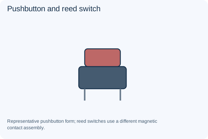
What it does
A pushbutton changes contacts through manual movement; a reed switch responds to magnetic influence.
Example
A user control or position detector.
Important distinction
Normally open/closed and momentary/latching behavior must be specified.
Specifications to read
Contact or interface assignment, voltage/current, load type, keying, mechanical requirements and insulation.
A rating is a limit or condition, not a guarantee of suitability. Use the manufacturer's data sheet for the exact component and the equipment's schematic for its intended role.
PWM and H-bridgeCommon Circuits
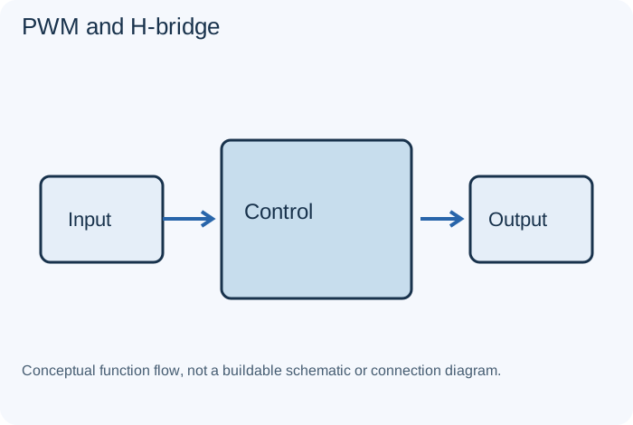
What it does
PWM controls time proportion; an H-bridge controls load polarity in an appropriate drive system.
Example
A documented motor-control trainer.
Important distinction
Switch timing and shoot-through prevention are essential design concerns.
Specifications to read
Intended function, source/load, operating range, component limits, response, stability, protection and layout.
A rating is a limit or condition, not a guarantee of suitability. Use the manufacturer's data sheet for the exact component and the equipment's schematic for its intended role.
Quartz crystalClocks and Resonators
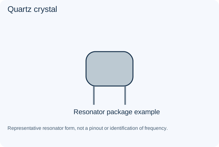
What it does
A resonator with specified frequency-related behavior, used within a compatible oscillator circuit.
Example
A microcontroller timing reference.
Important distinction
Load capacitance, drive level and oscillator compatibility matter.
Specifications to read
Frequency, accuracy, drive/load, supply where applicable, output format and oscillator compatibility.
A rating is a limit or condition, not a guarantee of suitability. Use the manufacturer's data sheet for the exact component and the equipment's schematic for its intended role.
RC timing networkCommon Circuits
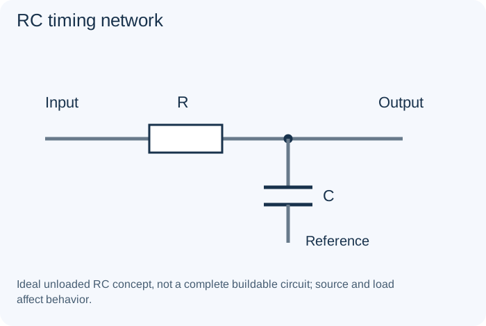
What it does
Uses resistance and capacitance to create time-dependent behavior.
Example
A delay or filter model.
Important distinction
The surrounding circuit determines the actual threshold and timing.
Specifications to read
Intended function, source/load, operating range, component limits, response, stability, protection and layout.
A rating is a limit or condition, not a guarantee of suitability. Use the manufacturer's data sheet for the exact component and the equipment's schematic for its intended role.
Receiver chain and feedback loopCommon Circuits
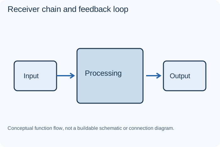
What it does
A receiver chain processes input into usable information. Feedback compares system behavior with a desired condition.
Example
A radio or regulated system.
Important distinction
One working block does not establish correct operation or stability of every connected stage.
Specifications to read
Intended function, source/load, operating range, component limits, response, stability, protection and layout.
A rating is a limit or condition, not a guarantee of suitability. Use the manufacturer's data sheet for the exact component and the equipment's schematic for its intended role.
Rectifier diodeDiodes
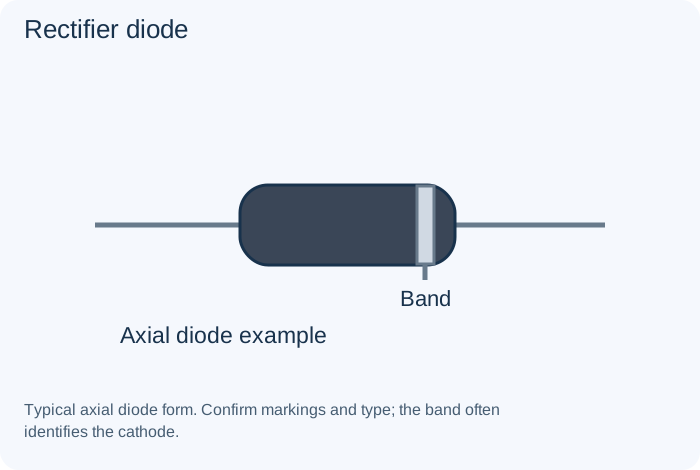
What it does
Conducts preferentially in one direction within its specified behavior, allowing rectification or directional current paths.
Example
Converting alternating input into unidirectional pulses.
Important distinction
Forward current, reverse voltage and recovery behavior must suit the circuit.
Specifications to read
Forward/reverse voltage behavior, current, dissipation, recovery or response and application-specific limits.
A rating is a limit or condition, not a guarantee of suitability. Use the manufacturer's data sheet for the exact component and the equipment's schematic for its intended role.
Rectifier tubeVacuum Tubes and Historical Parts
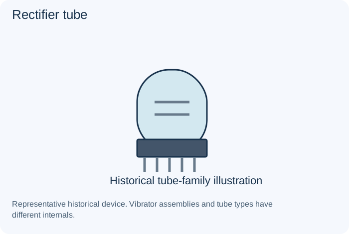
What it does
A tube selected to supply rectifying functions in a power arrangement.
Example
An older radio power supply.
Important distinction
Replacement can alter operating conditions; it is not merely a base-shape comparison.
Specifications to read
Exact type, pinout, heater and operating requirements, circuit role and model-specific service data.
A rating is a limit or condition, not a guarantee of suitability. Use the manufacturer's data sheet for the exact component and the equipment's schematic for its intended role.
Resettable polymer protectorProtection Parts
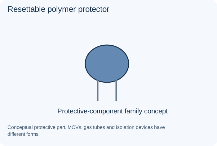
What it does
A temperature/current-dependent protective device that increases resistance under specified conditions.
Example
A limited-energy protection arrangement.
Important distinction
It has hold/trip and environmental requirements and is not identical to a conventional fuse.
Specifications to read
Approved function, ratings, fault behavior, breaking/energy capability and required protection coordination.
A rating is a limit or condition, not a guarantee of suitability. Use the manufacturer's data sheet for the exact component and the equipment's schematic for its intended role.
Reverse-polarity protectionProtection Parts
What it does
A circuit function that limits consequences of an incorrect source orientation using a suitable design.
Example
A protected DC input.
Important distinction
Protection topology, drop, current and failure behavior must be assessed.
Specifications to read
Approved function, ratings, fault behavior, breaking/energy capability and required protection coordination.
A rating is a limit or condition, not a guarantee of suitability. Use the manufacturer's data sheet for the exact component and the equipment's schematic for its intended role.
RF mixerCommon Circuits
What it does
Combines signals in a nonlinear or switching arrangement to obtain translated frequency components.
Example
A superheterodyne receiver.
Important distinction
Desired output selection, isolation and unwanted products matter.
Specifications to read
Intended function, source/load, operating range, component limits, response, stability, protection and layout.
A rating is a limit or condition, not a guarantee of suitability. Use the manufacturer's data sheet for the exact component and the equipment's schematic for its intended role.
RLC resonant circuitCommon Circuits
What it does
Combines resistance, inductance and capacitance to obtain frequency-dependent resonant behavior.
Example
A tuned receiver network.
Important distinction
Loss and loading change bandwidth and response.
Specifications to read
Intended function, source/load, operating range, component limits, response, stability, protection and layout.
A rating is a limit or condition, not a guarantee of suitability. Use the manufacturer's data sheet for the exact component and the equipment's schematic for its intended role.
Rotary encoder versus rotary switchSwitches, Relays and Connectors
What it does
An encoder reports movement or position as encoded information; a rotary switch selects contact paths.
Example
A menu knob or source selector.
Important distinction
Similar mechanical movement does not imply the same interface.
Specifications to read
Contact or interface assignment, voltage/current, load type, keying, mechanical requirements and insulation.
A rating is a limit or condition, not a guarantee of suitability. Use the manufacturer's data sheet for the exact component and the equipment's schematic for its intended role.
Schottky diodeDiodes
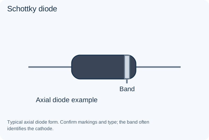
What it does
Uses a metal-semiconductor junction and has characteristics that can suit selected low-loss or fast applications.
Example
A converter or signal clamp.
Important distinction
Compare leakage, voltage and thermal requirements, not just forward drop.
Specifications to read
Forward/reverse voltage behavior, current, dissipation, recovery or response and application-specific limits.
A rating is a limit or condition, not a guarantee of suitability. Use the manufacturer's data sheet for the exact component and the equipment's schematic for its intended role.
SCR and triacTransistors and Controlled Switches
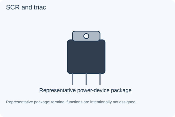
What it does
An SCR is a controlled thyristor with latching behavior; a triac supports a related bidirectional switching function.
Example
A documented controlled-power circuit.
Important distinction
These devices are not ordinary transistor replacements; hazardous power circuits need qualified work.
Specifications to read
Pinout, drive conditions, voltage/current, losses, temperature and safe operating limits.
A rating is a limit or condition, not a guarantee of suitability. Use the manufacturer's data sheet for the exact component and the equipment's schematic for its intended role.
Series circuitCommon Circuits
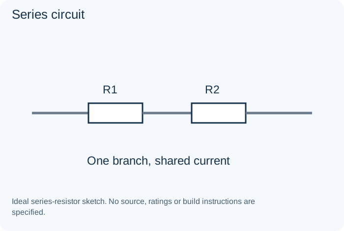
What it does
Connects elements along one current path in the ideal circuit model.
Example
Adding resistances along a branch.
Important distinction
Shared current does not mean every element has the same voltage.
Specifications to read
Intended function, source/load, operating range, component limits, response, stability, protection and layout.
A rating is a limit or condition, not a guarantee of suitability. Use the manufacturer's data sheet for the exact component and the equipment's schematic for its intended role.
Seven-segment displayPower Sources and Outputs
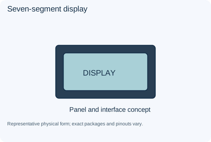
What it does
Groups visual segments into numeric or limited character indications.
Example
A counter or meter.
Important distinction
Common-anode/common-cathode and drive requirements differ.
Specifications to read
Source/load compatibility, polarity, current, chemistry where relevant, interface, mechanical and thermal conditions.
A rating is a limit or condition, not a guarantee of suitability. Use the manufacturer's data sheet for the exact component and the equipment's schematic for its intended role.
Signal generator and logic probeTest Equipment
What it does
A generator supplies a defined stimulus; a logic probe observes supported digital states.
Example
Signal-path or logic study.
Important distinction
Check signal levels, reference and loading before connecting equipment.
Specifications to read
Supported modes, input limits, probes, reference/ground, bandwidth or test conditions and appropriate training.
A rating is a limit or condition, not a guarantee of suitability. Use the manufacturer's data sheet for the exact component and the equipment's schematic for its intended role.
Snubber networkCommon Circuits
What it does
Controls selected switching transients through a circuit-specific dissipative or reactive arrangement.
Example
A qualified switching design.
Important distinction
Values and ratings must come from the actual application, not a universal recipe.
Specifications to read
Intended function, source/load, operating range, component limits, response, stability, protection and layout.
A rating is a limit or condition, not a guarantee of suitability. Use the manufacturer's data sheet for the exact component and the equipment's schematic for its intended role.
Socket, jumper and test pointSwitches, Relays and Connectors
What it does
A socket holds a removable component, a jumper selects a connection, and a test point provides access to a defined node.
Example
Service access or configuration.
Important distinction
An accessible node is not automatically a safe reference or an authorized connection.
Specifications to read
Contact or interface assignment, voltage/current, load type, keying, mechanical requirements and insulation.
A rating is a limit or condition, not a guarantee of suitability. Use the manufacturer's data sheet for the exact component and the equipment's schematic for its intended role.
Solid-state relaySwitches, Relays and Connectors
What it does
Uses semiconductor switching controlled through an input arrangement, often with isolation features.
Example
A suitable automated-load circuit.
Important distinction
Output technology, leakage, heat and AC/DC suitability vary.
Specifications to read
Contact or interface assignment, voltage/current, load type, keying, mechanical requirements and insulation.
A rating is a limit or condition, not a guarantee of suitability. Use the manufacturer's data sheet for the exact component and the equipment's schematic for its intended role.
SpeakerPower Sources and Outputs
What it does
Converts an electrical audio signal into sound through its transducer mechanism.
Example
An amplifier output load.
Important distinction
Impedance, power, enclosure and output topology influence suitability.
Specifications to read
Source/load compatibility, polarity, current, chemistry where relevant, interface, mechanical and thermal conditions.
A rating is a limit or condition, not a guarantee of suitability. Use the manufacturer's data sheet for the exact component and the equipment's schematic for its intended role.
SPST and SPDT switchSwitches, Relays and Connectors
What it does
SPST provides a single switched path; SPDT selects between two paths from a common pole.
Example
On/off control or signal selection.
Important distinction
Contact rating, load type and required isolation matter.
Specifications to read
Contact or interface assignment, voltage/current, load type, keying, mechanical requirements and insulation.
A rating is a limit or condition, not a guarantee of suitability. Use the manufacturer's data sheet for the exact component and the equipment's schematic for its intended role.
Stepper and servo systemPower Sources and Outputs
What it does
A stepper moves through driven phase sequences; a servo uses a feedback/control arrangement to achieve a commanded result.
Example
An instrument or positioning trainer.
Important distinction
A servo is a system concept, not simply a motor with a different connector.
Specifications to read
Source/load compatibility, polarity, current, chemistry where relevant, interface, mechanical and thermal conditions.
A rating is a limit or condition, not a guarantee of suitability. Use the manufacturer's data sheet for the exact component and the equipment's schematic for its intended role.
Strain gauge and load cellSensors and Transducers
What it does
A strain-sensitive element and associated assembly convert mechanical deformation into a measurable electrical change.
Example
Weight or force measurement.
Important distinction
Calibration, mounting and signal conditioning affect accuracy.
Specifications to read
Measured quantity/reference, range, accuracy, response, supply/bias, interface, calibration and environment.
A rating is a limit or condition, not a guarantee of suitability. Use the manufacturer's data sheet for the exact component and the equipment's schematic for its intended role.
Supercapacitor and safety capacitorCapacitors
What it does
A supercapacitor supports large charge storage in suitable low-voltage designs. Safety capacitors have specific interference-suppression approvals and application classes.
Example
Backup energy or approved line-interference suppression.
Important distinction
These are different families; a high voltage marking alone is not a safety approval.
Specifications to read
Capacitance (F), tolerance, voltage, polarity, dielectric, ESR, leakage, ripple capability and temperature conditions.
A rating is a limit or condition, not a guarantee of suitability. Use the manufacturer's data sheet for the exact component and the equipment's schematic for its intended role.
Switching-regulator ICIntegrated Circuits
What it does
Controls switching energy conversion, often with external magnetic and passive components.
Example
A buck, boost or other converter.
Important distinction
Topology, compensation, layout and protection must work together.
Specifications to read
Exact part/revision, pinout, supply, input/output ranges, timing, interface, thermal limits and required surrounding parts.
A rating is a limit or condition, not a guarantee of suitability. Use the manufacturer's data sheet for the exact component and the equipment's schematic for its intended role.
Tantalum capacitorCapacitors
What it does
Uses tantalum-based construction, usually with a polarized form. Device technology and application limits vary.
Example
Compact supply storage on a circuit board.
Important distinction
Polarity and surge/application requirements are essential selection criteria.
Specifications to read
Capacitance (F), tolerance, voltage, polarity, dielectric, ESR, leakage, ripple capability and temperature conditions.
A rating is a limit or condition, not a guarantee of suitability. Use the manufacturer's data sheet for the exact component and the equipment's schematic for its intended role.
Tetrode and pentodeVacuum Tubes and Historical Parts
What it does
Tube families with additional grid structures that affect their operating characteristics.
Example
A receiver or audio power stage.
Important distinction
Pinout and stage requirements must come from the exact tube and circuit data.
Specifications to read
Exact type, pinout, heater and operating requirements, circuit role and model-specific service data.
A rating is a limit or condition, not a guarantee of suitability. Use the manufacturer's data sheet for the exact component and the equipment's schematic for its intended role.
Thermal fuse and thermostatProtection Parts
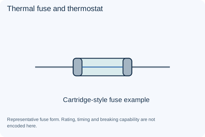
What it does
A thermal fuse provides a specified non-resetting interruption; a thermostat has a defined temperature-switching behavior.
Example
Overtemperature protection.
Important distinction
Do not bridge either device or substitute one without the design requirements.
Specifications to read
Approved function, ratings, fault behavior, breaking/energy capability and required protection coordination.
A rating is a limit or condition, not a guarantee of suitability. Use the manufacturer's data sheet for the exact component and the equipment's schematic for its intended role.
Thermocouple and RTDSensors and Transducers
What it does
A thermocouple produces a temperature-related voltage; an RTD uses a calibrated resistance-temperature relationship.
Example
Temperature instrumentation.
Important distinction
Both need suitable measurement circuits; they are not equivalent interfaces.
Specifications to read
Measured quantity/reference, range, accuracy, response, supply/bias, interface, calibration and environment.
A rating is a limit or condition, not a guarantee of suitability. Use the manufacturer's data sheet for the exact component and the equipment's schematic for its intended role.
Thick-film and thin-film resistorResistors
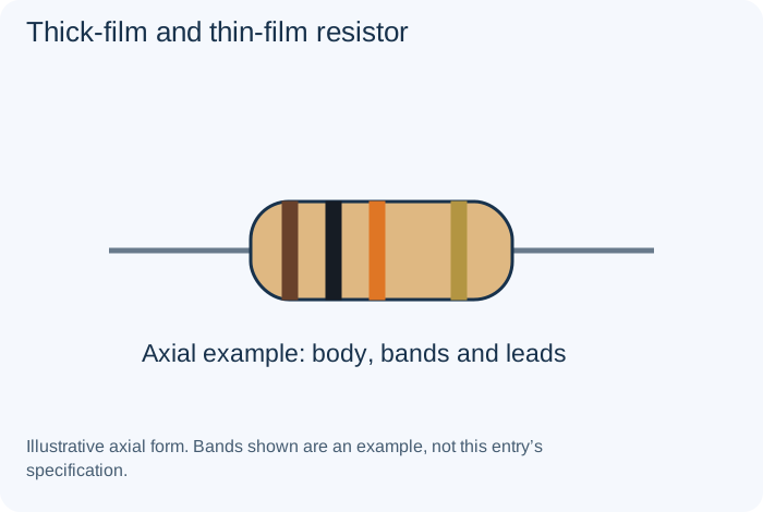
What it does
Distinct film constructions with different available precision, stability and application characteristics.
Example
A board-level signal network.
Important distinction
Use the exact series specifications; construction is not a complete rating.
Specifications to read
Resistance (Ω), tolerance (%), power (W), working voltage, temperature coefficient and pulse behavior.
A rating is a limit or condition, not a guarantee of suitability. Use the manufacturer's data sheet for the exact component and the equipment's schematic for its intended role.
Timer ICIntegrated Circuits
What it does
Combines timing-related functions in an integrated device; some familiar types use external resistors and capacitors.
Example
A pulse or timing circuit.
Important distinction
Use the actual device's modes and limits rather than a universal pin diagram.
Specifications to read
Exact part/revision, pinout, supply, input/output ranges, timing, interface, thermal limits and required surrounding parts.
A rating is a limit or condition, not a guarantee of suitability. Use the manufacturer's data sheet for the exact component and the equipment's schematic for its intended role.
TransformerInductors and Transformers
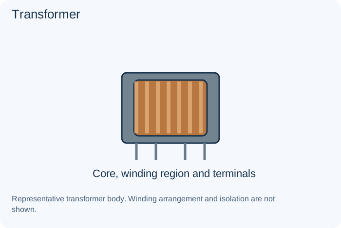
What it does
Transfers energy or signals through magnetic coupling between windings. Some designs provide electrical isolation; others do not.
Example
An isolated supply or audio coupling stage.
Important distinction
A transformer name or turns ratio does not establish safety isolation.
Specifications to read
Inductance, winding resistance, current, saturation, frequency, losses, coupling and required insulation.
A rating is a limit or condition, not a guarantee of suitability. Use the manufacturer's data sheet for the exact component and the equipment's schematic for its intended role.
Transistor safe operating areaTransistors and Controlled Switches
What it does
A specification describing permitted combinations of operating conditions within stated limits.
Example
A power-device suitability review.
Important distinction
A maximum current number alone is not a safe operating guarantee.
Specifications to read
Pinout, drive conditions, voltage/current, losses, temperature and safe operating limits.
A rating is a limit or condition, not a guarantee of suitability. Use the manufacturer's data sheet for the exact component and the equipment's schematic for its intended role.
Transistor switch and driverCommon Circuits
What it does
Controls a load through an active device and suitable drive/protection network.
Example
A low-voltage indicator or relay trainer.
Important distinction
Drive capability and inductive-load behavior must be considered.
Specifications to read
Intended function, source/load, operating range, component limits, response, stability, protection and layout.
A rating is a limit or condition, not a guarantee of suitability. Use the manufacturer's data sheet for the exact component and the equipment's schematic for its intended role.
Trimmer and resistor networkResistors
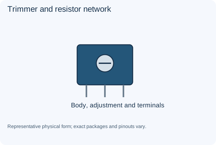
What it does
A trimmer supports occasional adjustment; a network combines several resistors in one package.
Example
Calibration or multiple digital-input pull-ups.
Important distinction
Check internal connections; some networks share a common terminal.
Specifications to read
Resistance (Ω), tolerance (%), power (W), working voltage, temperature coefficient and pulse behavior.
A rating is a limit or condition, not a guarantee of suitability. Use the manufacturer's data sheet for the exact component and the equipment's schematic for its intended role.
TriodeVacuum Tubes and Historical Parts
What it does
A thermionic tube with a control-grid function in addition to cathode and plate.
Example
A historical amplifier or oscillator.
Important distinction
A tube envelope may contain several sections with separate roles.
Specifications to read
Exact type, pinout, heater and operating requirements, circuit role and model-specific service data.
A rating is a limit or condition, not a guarantee of suitability. Use the manufacturer's data sheet for the exact component and the equipment's schematic for its intended role.
TVS diodeDiodes
What it does
Designed to suppress specified transient events by limiting voltage during those events.
Example
An interface protection network.
Important distinction
It is not a substitute for a steady-state voltage regulator.
Specifications to read
Forward/reverse voltage behavior, current, dissipation, recovery or response and application-specific limits.
A rating is a limit or condition, not a guarantee of suitability. Use the manufacturer's data sheet for the exact component and the equipment's schematic for its intended role.
Vacuum diodeVacuum Tubes and Historical Parts
What it does
A thermionic two-electrode device that can rectify in its intended circuit.
Example
A historical receiver supply.
Important distinction
Heater and operating requirements differ from semiconductor diode requirements.
Specifications to read
Exact type, pinout, heater and operating requirements, circuit role and model-specific service data.
A rating is a limit or condition, not a guarantee of suitability. Use the manufacturer's data sheet for the exact component and the equipment's schematic for its intended role.
Varactor and PIN diodeDiodes
What it does
A varactor provides voltage-dependent junction capacitance. A PIN diode has a structure useful in selected RF or detection applications.
Example
Electronic tuning or RF switching.
Important distinction
These are distinct devices with application-specific behavior.
Specifications to read
Forward/reverse voltage behavior, current, dissipation, recovery or response and application-specific limits.
A rating is a limit or condition, not a guarantee of suitability. Use the manufacturer's data sheet for the exact component and the equipment's schematic for its intended role.
Variable and trimmer capacitorCapacitors
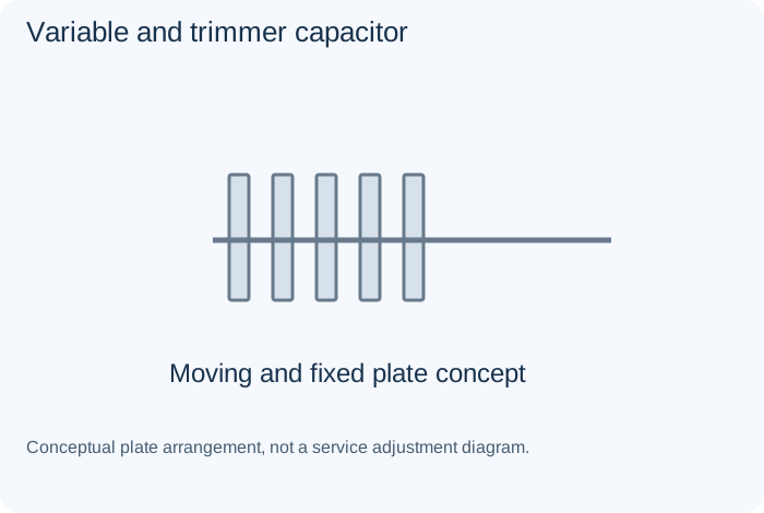
What it does
Changes capacitance mechanically or by an adjustable structure, allowing tuning or calibration.
Example
An older radio tuning assembly.
Important distinction
Mechanical range and circuit function must match the design.
Specifications to read
Capacitance (F), tolerance, voltage, polarity, dielectric, ESR, leakage, ripple capability and temperature conditions.
A rating is a limit or condition, not a guarantee of suitability. Use the manufacturer's data sheet for the exact component and the equipment's schematic for its intended role.
Vibrator unitVacuum Tubes and Historical Parts
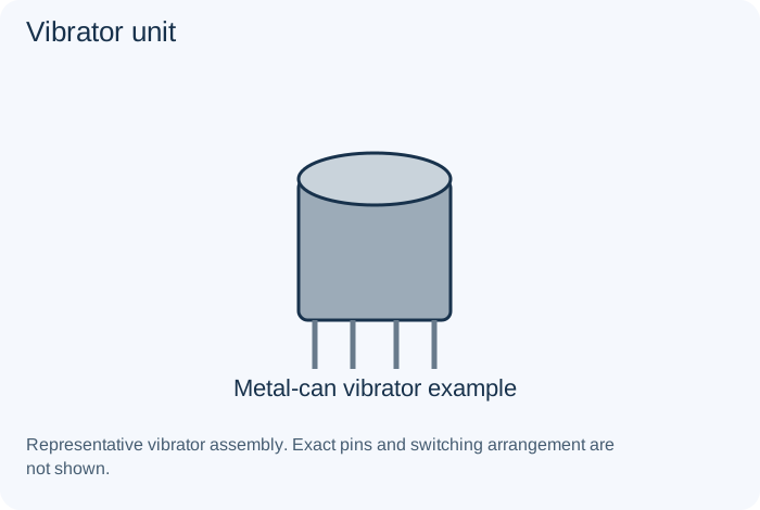
What it does
An electromechanical switching device used in some historical battery-powered supplies.
Example
A vintage car-radio supply.
Important distinction
Mechanical buzzing does not prove correct electrical output or suitability.
Specifications to read
Exact type, pinout, heater and operating requirements, circuit role and model-specific service data.
A rating is a limit or condition, not a guarantee of suitability. Use the manufacturer's data sheet for the exact component and the equipment's schematic for its intended role.
Voltage dividerCommon Circuits
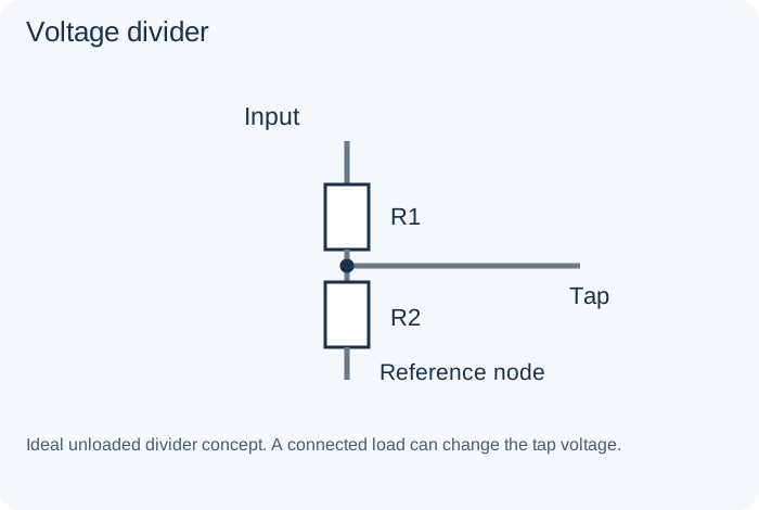
What it does
Uses a ratio of impedances to obtain a portion of an input voltage.
Example
A measurement input.
Important distinction
A connected load can change the ratio; it is not a general power supply.
Specifications to read
Intended function, source/load, operating range, component limits, response, stability, protection and layout.
A rating is a limit or condition, not a guarantee of suitability. Use the manufacturer's data sheet for the exact component and the equipment's schematic for its intended role.
Voltage referenceIntegrated Circuits
What it does
Provides a specified reference level for suitable measurement or control arrangements.
Example
An ADC reference input.
Important distinction
Accuracy, load, temperature behavior and noise affect the result.
Specifications to read
Exact part/revision, pinout, supply, input/output ranges, timing, interface, thermal limits and required surrounding parts.
A rating is a limit or condition, not a guarantee of suitability. Use the manufacturer's data sheet for the exact component and the equipment's schematic for its intended role.
Wheatstone bridgeCommon Circuits
What it does
Uses a comparison of branch relationships to detect a resistance-related change or imbalance.
Example
A strain-gauge measurement.
Important distinction
Excitation, loading and calibration affect the result.
Specifications to read
Intended function, source/load, operating range, component limits, response, stability, protection and layout.
A rating is a limit or condition, not a guarantee of suitability. Use the manufacturer's data sheet for the exact component and the equipment's schematic for its intended role.
Wirewound resistorResistors
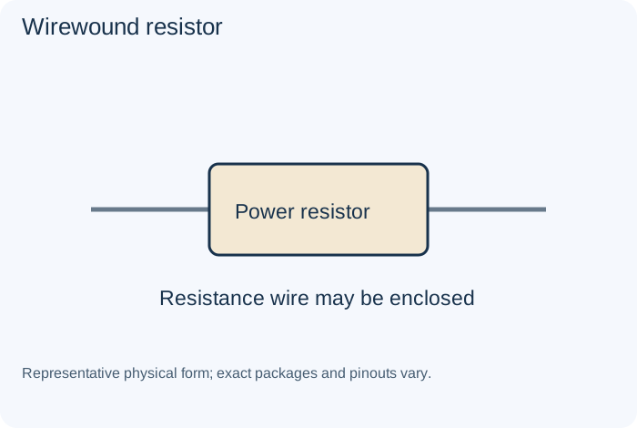
What it does
Uses resistance wire wound on a supporting form. Construction can introduce inductance as well as resistance.
Example
A power load or historical supply resistor.
Important distinction
A part suited to DC may not suit a high-frequency circuit.
Specifications to read
Resistance (Ω), tolerance (%), power (W), working voltage, temperature coefficient and pulse behavior.
A rating is a limit or condition, not a guarantee of suitability. Use the manufacturer's data sheet for the exact component and the equipment's schematic for its intended role.
X-class safety capacitorCapacitors
What it does
An interference-suppression capacitor approved for its specified across-line application class.
Example
An approved mains interference network.
Important distinction
Use the required approvals and class; it is not a general-purpose capacitor substitution.
Specifications to read
Capacitance (F), tolerance, voltage, polarity, dielectric, ESR, leakage, ripple capability and temperature conditions.
A rating is a limit or condition, not a guarantee of suitability. Use the manufacturer's data sheet for the exact component and the equipment's schematic for its intended role.
X7R and X5R ceramic dielectricCapacitors
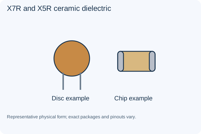
What it does
Ceramic classifications describing specified temperature behavior; capacitance can also depend on operating bias.
Example
Compact supply decoupling.
Important distinction
The marked nominal value is not necessarily the effective value in the actual circuit.
Specifications to read
Capacitance (F), tolerance, voltage, polarity, dielectric, ESR, leakage, ripple capability and temperature conditions.
A rating is a limit or condition, not a guarantee of suitability. Use the manufacturer's data sheet for the exact component and the equipment's schematic for its intended role.
Y-class safety capacitorCapacitors
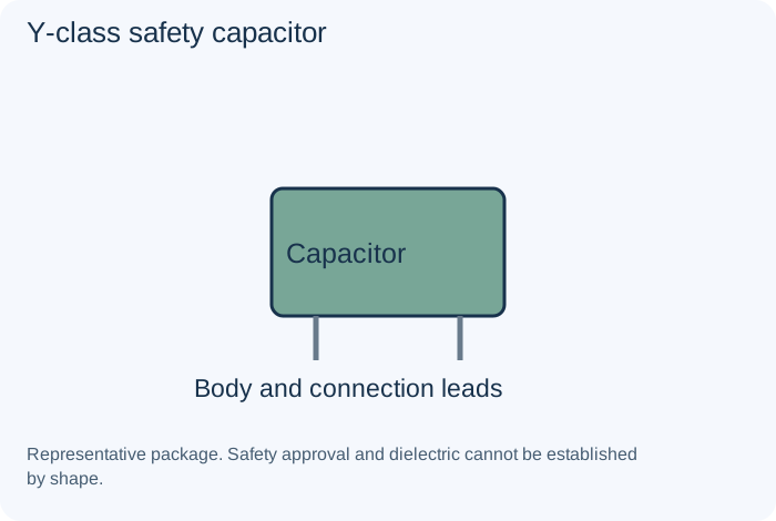
What it does
An interference-suppression capacitor approved for specified applications involving an isolation or line-to-earth relationship.
Example
An approved interference path.
Important distinction
Required class, leakage and system safety must be preserved by qualified personnel.
Specifications to read
Capacitance (F), tolerance, voltage, polarity, dielectric, ESR, leakage, ripple capability and temperature conditions.
A rating is a limit or condition, not a guarantee of suitability. Use the manufacturer's data sheet for the exact component and the equipment's schematic for its intended role.
Zener diodeDiodes
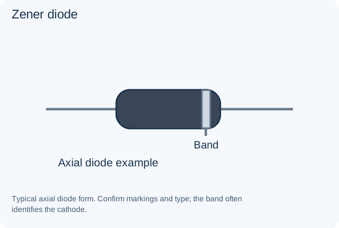
What it does
Operates in a specified reverse-breakdown region for reference or limiting applications.
Example
A suitably designed voltage reference.
Important distinction
It needs a compatible current-limiting and power-dissipation arrangement.
Specifications to read
Forward/reverse voltage behavior, current, dissipation, recovery or response and application-specific limits.
A rating is a limit or condition, not a guarantee of suitability. Use the manufacturer's data sheet for the exact component and the equipment's schematic for its intended role.
Zero-ohm linkResistors
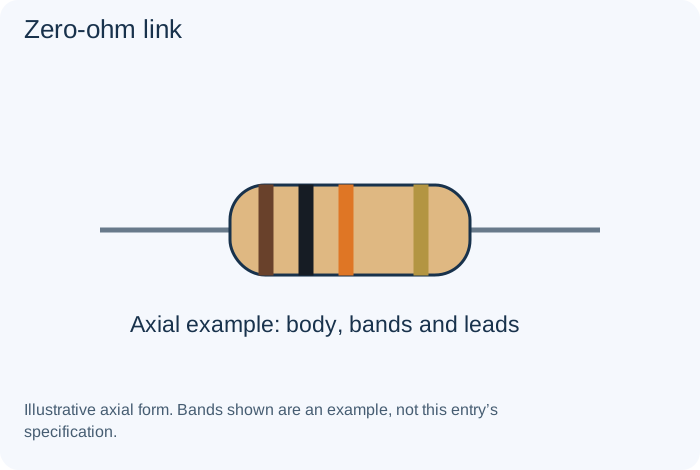
What it does
A component used as a defined connection rather than a precision resistance.
Example
Routing a board connection.
Important distinction
Current and thermal limits still apply.
Specifications to read
Resistance (Ω), tolerance (%), power (W), working voltage, temperature coefficient and pulse behavior.
A rating is a limit or condition, not a guarantee of suitability. Use the manufacturer's data sheet for the exact component and the equipment's schematic for its intended role.
Visual comparison guides
Compare representative physical forms, then read the entries for their different functions. Many parts share package shapes. Appearance alone cannot identify ratings, internal construction or terminal assignments.
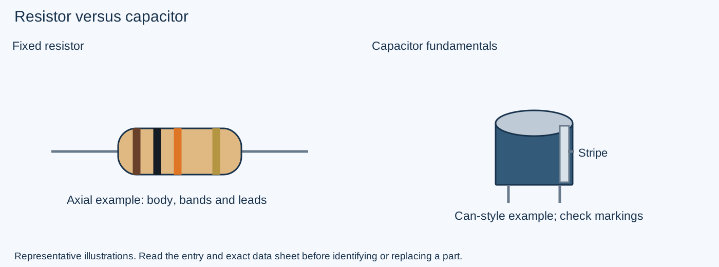
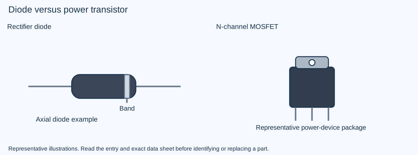
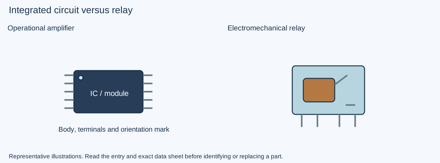
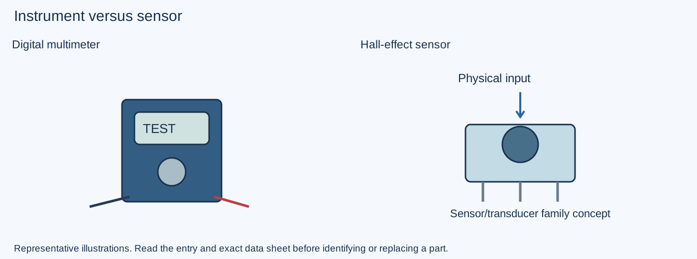
Units and worked examples
| Quantity | Unit | Meaning |
|---|---|---|
| Voltage | V, volts | Potential difference between two points. |
| Current | A, amperes | Rate of charge flow. |
| Resistance | Ω, ohms | Resistance to current flow. |
| Power | W, watts | Rate of energy transfer or dissipation. |
| Capacitance | F, farads | Charge change per voltage change. |
| Inductance | H, henries | Relationship between current change and induced voltage. |
| Frequency | Hz, hertz | Cycles per second. |
Prefixes: k = 1,000; M = 1,000,000; m = 0.001; μ = 0.000001; n = 0.000000001; p = 0.000000000001. Case matters: M and m are different.
Resistor example
For an ideal 1 kΩ resistor with 5 V across it: I = V/R = 5/1,000 = 0.005 A = 5 mA. Dissipation is P = V²/R = 25/1,000 = 0.025 W. This arithmetic does not select a real part without its temperature, voltage and application requirements.
Tolerance example
A 1 kΩ resistor with ±5% nominal tolerance spans 950 Ω to 1,050 Ω at the specified conditions. Tolerance is different from drift with temperature or aging.
Capacitance and timing example
10 μF = 10,000 nF. An ideal first-order RC network with R = 1 kΩ and C = 10 μF has τ = RC = 0.01 s = 10 ms. A time constant is not automatically the delay of every timer using those parts.
Stored energy
Ideal capacitor charge is Q = CV; stored energy is E = ½CV². Doubling voltage at the same capacitance quadruples the stored energy. These are learning equations, not a discharge procedure.
Schematic symbols, labels and markings
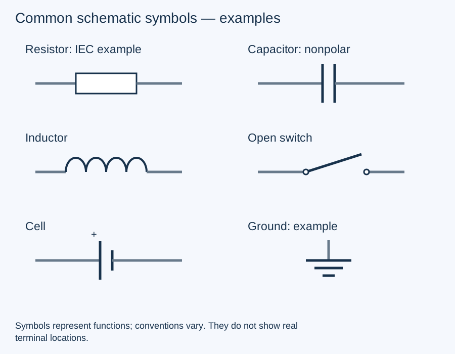
Reference letters identify components in a drawing; conventions vary by manufacturer and standard. Always read the drawing's legend.
| Common label | Often used for |
|---|---|
| R | Resistor |
| C | Capacitor |
| L | Inductor |
| D | Diode |
| Q | Transistor |
| U / IC | Integrated circuit |
| T | Transformer |
| K / RL | Relay |
| SW / S | Switch |
| J / P / CN | Connector |
| F | Fuse |
| Y / X | Crystal or resonator |
| TP | Test point |
| V / VT | Tube in some historical documentation |
R17 identifies a component location, not a resistance value. A marking such as 4R7 may mean 4.7 Ω in an applicable resistor convention. Three-digit markings such as 104 often represent 100,000 base units: 100 kΩ for a resistor or 100,000 pF = 100 nF for an applicable capacitor code. Confirm the component family and marking system; short codes can be ambiguous.
Common questions
Can I replace a part with any higher-rated one?
No. A higher headline rating does not ensure suitable function, polarity, frequency behavior, package, protective approval or circuit stability.
Does a part that looks normal have to be good?
No. Visual observations can help, but many electrical changes leave no obvious external sign.
Are capacitance, ESR and leakage the same?
No. They describe different properties. A single test cannot establish every capacitor failure mode.
Can I measure every component while it remains connected?
Other paths can affect an in-circuit result. Interpretation depends on the circuit and instrument. Internal work also requires a suitable qualified safety procedure.
Does a matching package establish a transistor or IC replacement?
No. Pinout, function, voltage, drive, timing, heat and application requirements must match.
Is a component the same thing as a circuit?
A component is a building block. A circuit connects building blocks to perform a function. The same component family can serve many circuit roles.
How do I begin learning?
Start with units, schematic labels, resistor/capacitor/inductor functions and signal-versus-power paths. Use disconnected parts or an instructor-approved low-voltage trainer before considering customer equipment.
Is this reference free?
Yes. Every entry, example and reference on this page is public. The separate repair masterclasses have their own free previews and paid lessons.
Manufacturer references
Original plain-language summaries and educational examples. These references support further study; exact product data sheets and equipment manuals remain authoritative for a real application.
Save to Pinterest